1997 HONDA CIVIC Code 38
[x] Cancel search: Code 38Page 1471 of 2189

l'f .
Electrical
Special Toofs .,....................,23-2
Troubleshooting
Tips and Precautions ..............,.................... . 23-3
Five-step Troubleshooting .............. ......... . . 23-5
wire color codes ..........,23-5
Schematic Symbols ........,................... . . .. .... 23-6
Relay and Control Unit Locations
Engine Compartment ...,..................... ... .. . 23'7
Dashboard ......................23-8
Dashboard/Door ......... 23-12*Airbags ................. ....... Section 24
Air Conditioning ......... Section 21
Aftelnator ..........."""" """ 23-112
Anti-lock Brake System {ABS) Section 19*A/T Gear Position Indicator .....................,. .... ... 23-149
Automatic Transmission Svstem .... . ....... Section 14
Batterv ......... . . . ... ...... .......23-91
Blower controls .. . ... Section 2l
Charging System ....'...........23'112
Connector ldentilication and Wire Harness
Routing .................. ......23'13
Cruise Control ............,........23-240
Dash Lights Brightness Controller ............. ....... 23-180
Fan controfs "" 23'126
Fuel PumD ........ . ........ section 11
Fuses/Refay ...............,..,,.. 23'62
PGM-FI Control System ......................,....... Section 1 1
*Gauges
Circuit Diagram ....,.,.......23-131
Fuef Gauge ...........'.'.......23-142
Gauge/lndicator .. . .. 23-129
Ground Distribution .. . 23-75
Heatei controls .. . ..... Section 21*Horn................. ...............23-196
*tgnition Switch ....................23-89
lgnition System .......,.... 23-102
*lntegrated Control Unit ....................................... 23-156
fnterlock System ,........ . . , ,23-144
Lighting System . . . .. ......... 23-161
Lights, Exterior
Back-up Lights ..'............23'171
Brake Lights .................. 23'174
Daytime Bunning Lights (Canadal ............... 23'166
Front Parking Lights ......,................ .'. .......... 23-167
Front Turn Signal Lights .......... . . ............ ..,.23-167
Headtights ....".'....-... ..... 23'167
High Mount Brake Light ...................... ... .23'179
License Plate Lights ...... 23'176
Taitfights ................ .......23'171
lnterior Lights ..-.......,, . 23-142
Moonroof ..,.................,........ 23-235
Power Distribution ....... . . .23-61
Power Door Locks .......,,,. .23'251
Power Mirrors ,..............,.,...23'206
Power Relays ....... . ...... . . .. 23-86
Power Windows ............,,....23-220
Rear Window Defogger .......................... . . ... . . 23-2OO
Spark Plugs . ..... . ........ .....23-111
Slarting System ................23-93*stereo Sound Svstem ,................. ..... ... . ... ,.,.,,23'147'Supplemental Restraint System (SRS) ... . Section 24
Turn Signal/Hazard Flasher System .......'.'....-... 23-173
*Undel-dash Fuse/Relay Box ............,.................. 23-85
vehicfe soeed sensor (VSSI """" ""' 23-140+Wipers/Washers .........,.,.,...23-214
NOTE: Unless otherwise specified, references to auto-
matic transmission (Mf) in this section include the CVT.
Page 1475 of 2189
t
Five-step Troubleshooting
2.
1.Verify The Complaint
Turn on all the components in the problem circuit to
verify the customer complaint. Note the symptoms.
Do not begin disassembly or testing until you have
narrowed down the problem area.
Analyze The Schematic
Look up the schematic for the problem circuit.
Determine how the circuit is supposed to work by
tracing the current paths from the power feed
through the circuit components to ground. lf several
circuits fail at the same time, the fuse or ground is a
likely cause.
Based on the symptoms and your understanding of
the circult operation, identify one or more possible
causes of the problem.
lsolate The Problem By Testing The Circuit
Make circuit tests to check the diagnosis you made
in step 2. Keep in mind that a logical, simple proce-
dure is the key to efficient troubleshooting. Test for
the most likely cause of failure first. Try to make
tests at points that are easily accessible.
Fix The Problem
Once the specific problem is identified, make the
repair. Be sure to use proper tools and safe proce-
dures.
Make Sure The Circuit Works
Turn on all components in the repaired circuit in all
modes to make sure you've fixed the entire prob-
lem. lf the problem was a blown fuse, be sure to
test all of the circuits on the fuse, Make sure no new
problems turn up and the original problem does not
recur.
3.
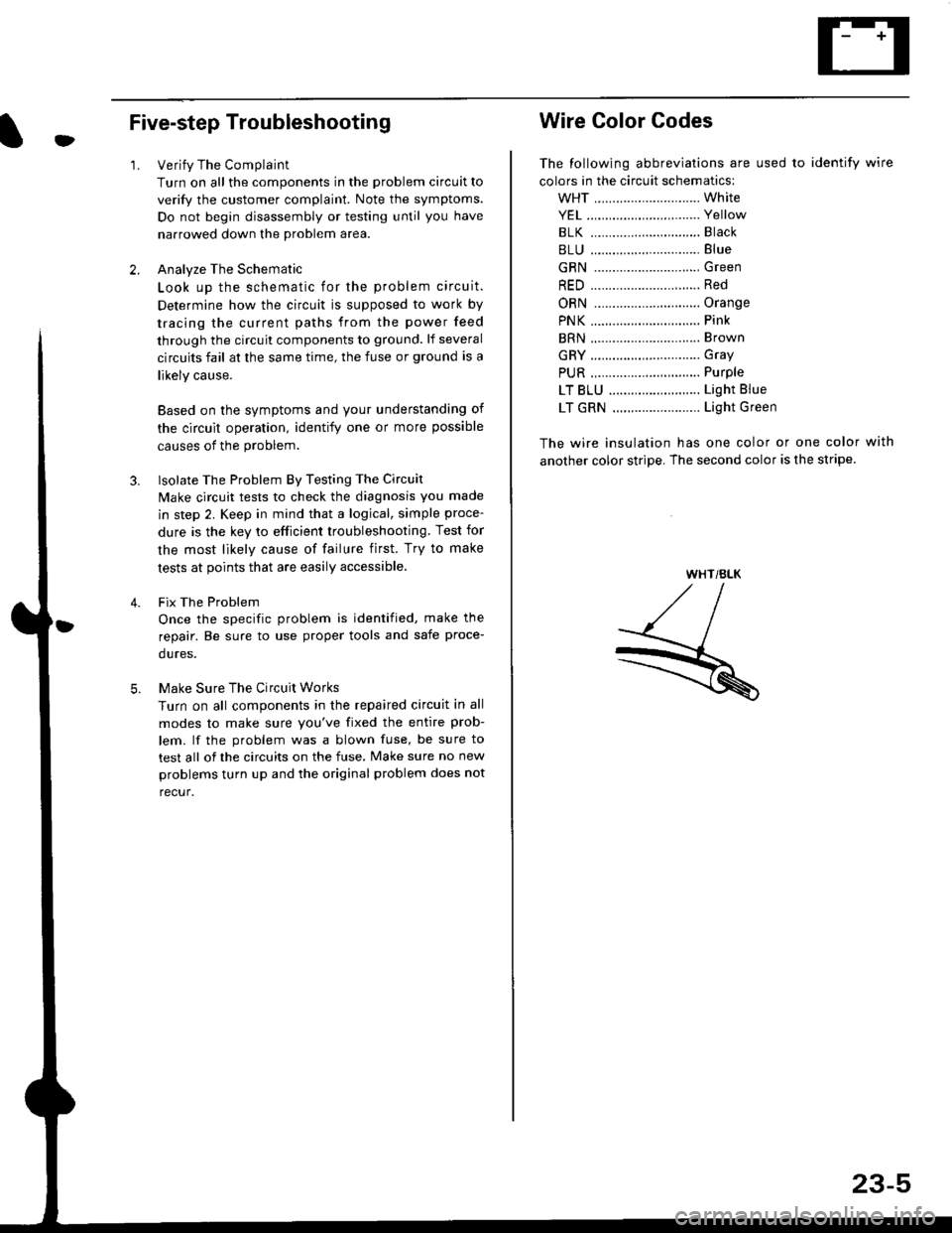
Wire Color Codes
The following abbreviations are used to identify wire
colors in the circuit schematics:
wHT ............................. White
YEL ............................... Yellow
BLK ............,.,...............81ack
BLU .............................. Blue
GRN .............................Green
RED .......................,...... Red
ORN ............................. Orange
PNK .............................. Pink
BRN .............................. Brown
GRY .............................. Gray
PUR .,.................,.,........ Purple
LT BLU ......................... Light Blue
LT GRN ........................ Light Green
The wire insulation has one color or one color with
another color stripe. The second color is the stripe.
WHT/BLK
23-5
Page 1555 of 2189
Under-dash Fuse/RelaY Box
Removal/lnstallation
SRS components are located in this area. Review lhe
SRS component locations, precautions, and procedures
in the SRS section (24) before performing repairs or ser-
vice.
Removal:
1. Make sure you have the anti-lheft code for the radio
then write down the frequencies lor the radio's pre-
set buttons ('99 - 00 modelsl.
2. Disconnect the battery negative cable. then discon
nect the positive cable, and wait at least three min
utes,
3. Disconnect the airbag connectors (see section 24)'
4. Remove the driver's dashboard lower cover and
knee bolster (see section 20)
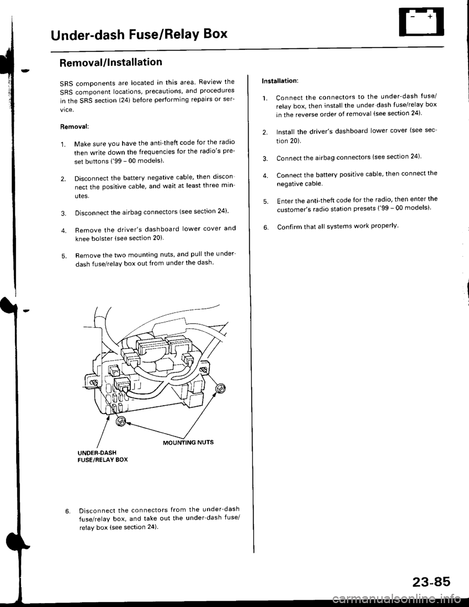
5. Remove the two mounting nuts, and pull the under
dash fuse/relay box out from under the dash'
6. Disconnect the connectors from the under-dash
fuse/relay box, and take out the under-dash fuse/
relay box (see section 24).
lnstallation:
1. Connect the connectors to the under-dash tuse/
relay box, then install the under dash fuse/relay box
in the reverse order of removal (see section 24)'
2. Install the driver's dashboard lower cover (see sec
tion 20).
3. Connect the airbag connectors {see section 24)
4. Connect the battery positive cable, then connect the
negative cable.
5. Enter the anti-theft code lor the radio, then enter the
customer's radio station presets ('99 - 00 models)'
6. Confirm that all sYstems work properly'
23-45
Page 1559 of 2189
lgnition Switch
4.
Test
SRS components are located in this area Review the
SRS component locations. precautions. and procedures
in the SRS section {24} before performing repairs or ser-
1. i/ake sure you have the anti-theft code for the
radio, then write down the frequencies for the
radio's preset buttons ('99 - 00 models).
2. Disconnect the battery negative cable.
3. Remove the driver's dashboard lower cover and
knee bolster (see section 20).
Disconnect the 5P connector from the under dash
fuse/relay box and the 7P connector from the main
wire harness.
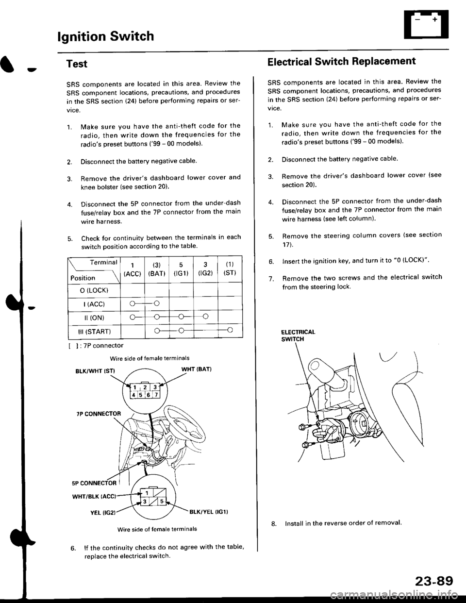
Check for continuity between the terminals in each
switch position according to the table.
I I :7P connector
Wire side ot female terminals
BLK/WHT {STIWHT IBAT}
7P CONNECTOR
WHT/BLK
YEL (IG2}BLK/YEL {IG1)
Wire side of female terminals
6. lf the continuity checks do not agree with the table,
replace the electrical switch.
Terminal
Position
1
(ACC)
(3)
(BAT)
5
{tG1) G2)
(1)
(sr)
o (LocK)
| (ACC)o--o
l (oN)o-o
III (START)o--o
1.
Electrical Switch RePlacement
SRS components are located in this area. Review the
SRS component locations, precautions, and procedures
in the SRS section \24) belore performing repairs or ser-
vtce.
1. Make sure you have the anti-theft code for the
radio, then write down the frequencies for the
radio's preset buttons {'99 - 00 modelsl.
2. Disconnect the battery negatlve cable.
3. Remove the driver's dashboard lower cover {see
section 20).
Disconnect the 5P connector from the under-dash
fuse/relay box and the 7P connector from the main
wire harness (see left column).
Remove the steering column covers {see section
11t.
lnsert the ignition key, and turn it to "0 {LOCK)".
Remove the two screws and the electrical switch
from the steering lock.
ELECTRICALswtTcH
8. Install in the reverse order of removal.
23-a9
Page 1560 of 2189
lgnition Switch
Steering Lock Replacement
SRS components are located in this area. Review theSRS component locations. precautions, and procedures
in the SRS section (24) before performing repairs or ser-vtce.
Remove:
LMake sure you have the anti-theft code for theradio, then wire down the frequencies for theradio's preset buttons ('99 - 00 models).
Disconnect the battery negative cable.
Remove the driver's dashboard lower cover andknee bolster (see section 20).
Disconnect the 5P connector from the under-dash
fuse/relay box and the 7P connector from the mainwire harness (see previous page).
Remove the steering column covers, then removethe mounting bolts and nuts from the steering col-umn (see section l7).
Lower the steering column assembly,
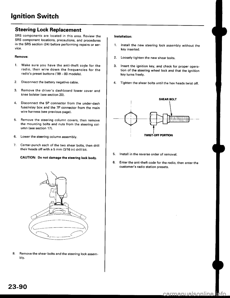
Center-punch each of the two shear bolts, then drilltheir heads off with a 5 mm (3/16 in) dritt bit.
CAUTION: Do not damago the steering lock body.
Remove the shear bolts and the steering lock assem,oty.
2.
1.
23-90
Installation:
l. Install the new steering lock assembly without thekey insened.
Loosely tighten the new shear bolts-
Insert the ignition key, and check for proper opera-tion of the steering wheel lock and that the ignitionkey turns freely.
Tighten the shear bolts untilthe hex heads twist off.
TWIST.OFF FORTION
Install in the reverse order of removar.
Enter the anti-theft code for the radio, then enter thecustomer's radio station presets.
sr{€aR SroLT
Page 1562 of 2189
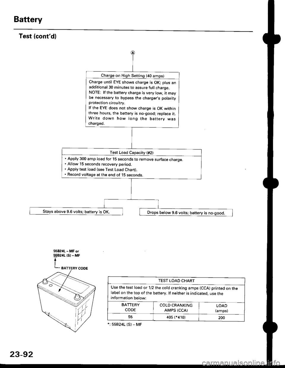
Battery
Test (cont'd)
Charge on High Sefting (40 amps)
Charge until EYE shows charge is OK; plus anadditional 30 minutes to assure full charge.NOTE: lf the battery charge is very tow, it maybe necessary to bypass the charger,s polarityprotection circuitry.
lf the EYE does not show charge is OK withinthree hours, the battery is no-good; replace it.Write down how long the battery wascharged.
Test Load Capacity (#2)
Apply 300 amp load for 15 seconds to remove surface charoe.Allow 15 seconds recovery period.
Apply test load {see Test Load Chan).
Record voltage at the end of 15 seconos.
Stays above 9.6 volts; battery is OK. ,] Drops below 9.6 volts; baftery is no-good.
tu,
TEST LOAD CHART
Use the test load or 1/2 the cold cranking amps {CCA) printed on thelabel on the top of the banery. lf neither is indicated. use theinformation below:
BArrERy coLb@
coDE I AMps (ccAl | {amps)
405 (*410)200
*:558241 (S) - MF
23-92
Page 1565 of 2189
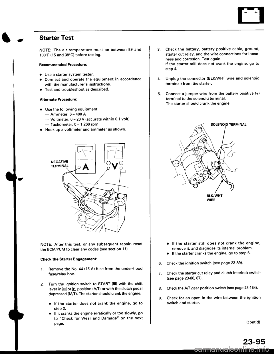
-Starter Test
NOTE; The air temoerature must be between 59 and
100'F (15 and 38"C) before testing.
Recommended Procedure:
. Use a staner system tester.
. Connect and operate the equipment in accordance
with the manufacturer's instructions.
. Test and troubleshoot as described,
Alternate Procedurg:
. Use the following equipment:- Ammeter, 0 - 400 A
- Voltmeter, 0 - 20 V (accurate within 0.1 volt)
- Tachometer, 0 - 1,200 rpm
. Hook up a voltmeter and ammeter as shown.
NEGATIVETERMINAL
NOTE: After this test, or any subsequent repair. reset
the ECM/PCM to clear any codes (see section l1)
Check the Start€r Engagemont:
1. Remove the No. 44 (15 A) fuse from the under-hood
fuse/relay box,
2. Turn the ignition switch to START (llll with the shift
lever in E or E position (rVT) or with the clutch pedal
depressed {M/T). The starter should crank the engine.
. lf the starter does not crank the engine, go to
step 3.
. lf itcranksthe engineerraticallyortooslowly, go
to "Check for Wear and Damage" on the next
page.
Check the battery. battery positive cable, ground,
starter cut relay, and the wire connections for loose-
ness and corrosion, Test again.
lf the starter still does not crank the engine, go to
step 4,
Unplug the connector (BLK,/WHT wire and solenoid
terminal) from the starter,
Connect a jumper wire from the battery positive (+)
terminal to the solenoid terminal.
The starter should crank the engine.
. lf the starter still does not crank the engine,
remove it, and diagnose its internal problem
. lf the startercranksthe engine, goto step 6.
Check the ignition switch (see page 23-891.
Check the starter cut relay and clutch interlock switch
(see page 23-86,87).
Check the A/f gear position switch (see page 23-154).
Check for an open in the wire between the ignition
switch and starter.
7.
(cont'd)
23-95
9.
Page 1570 of 2189
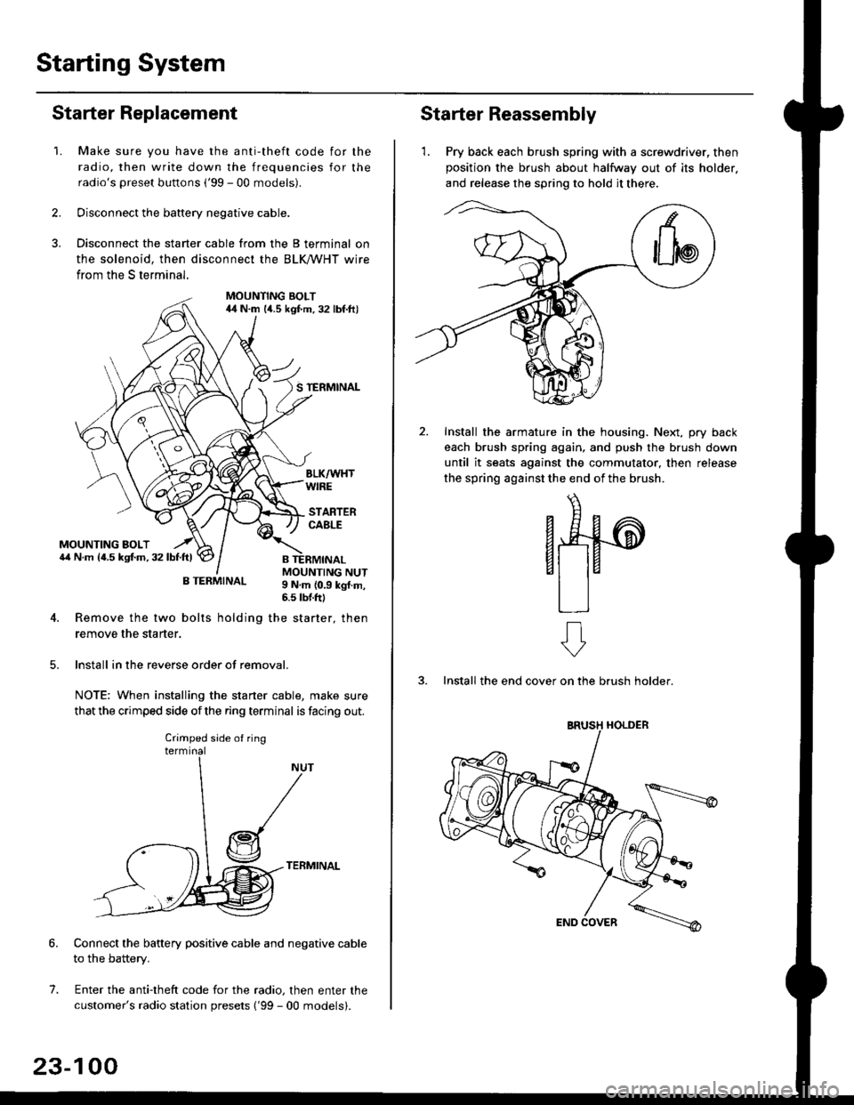
Starting System
Starter Replacement
1.Make sure you have the anti-theft code for the
radio, then write down the frequencies for the
radio's preset buttons ('99 - 00 models).
Disconnect the battery negative cable.
Disconnect the starter cable from the B terminal on
the solenoid, then disconnect the BLK trHT wire
from the S terminal.
MOUNTING BOLT44 N.m l/t.s kgf.m. 32 lbf.ft)
S TERMINAL
MOUNTING BOLT6,1 N.m {4.5 kstm.32lbtftl
MOUNTING NUT9 N,m {0.9 kgl.m,6.s lbtftl
B TERMINAL
4. Remove the two bolts holding the starter, then
remove the starter.
lnstall in the reverse order of removal.
NOTE: When installing the staner cable, make sure
that the crimped side ofthe ring terminal is facing out.
TERMINAL
Connect the battery positive cable and negative cable
to the battery.
Enter the anti-theft code for the radio, then enter the
customer's radio station presets ('99 - 00 models).
7.
Crimped side of ring
23-100
Starter Reassembly
'1. Pry back each brush spring with a screwdriver, then
position the brush about halfway out of its holder.
and release the spring to hold it there.
Install the armature in the housing. Next, pry back
each brush spring again, and push the brush down
until it seats against the commutator, then release
the spring against the end of the brush.
aw
3. Install the end cover on the brush holder.
ERUSH HOLDER