1997 HONDA CIVIC Connectors
[x] Cancel search: ConnectorsPage 1814 of 2189
SRS Unit
Replacement
CAUTION:
. Betore disconnoqting lny pErt of the SRS wire hal-ness, disconnect th9 airbag conn"ctorlsl.. During installltion or teplacemsnt. do not bump(impact w.cnch, hamm€r stc.l the area noar tho SRSunit.
NOTE:
o Do not damage the SRS unit terminals or connectors.. Do not disassemble the SRS unit; it has no service-able parts,
. Store the SRS unit in a clean, dry a.ea,. Do not use any SRS unit which has be€n subjected towater or shows signs of being dropped or improperlyhandled. such 8s dents, cracks or deformation.
1. Disconnect the bsttery negative cable. then discon-nect the positive cable from the battery, and wait atleast three minutes.
2. Disconnect the airbag connector{s}:
NOTE: When disconnected, the airbag connector isautomatically shorted,
Driver's Side:
. Remove the access panel from the steering wheel.then disconnect the 2P connector between the driv_er's airbag and cable reel (see page 24-11).
Front Passenge/s Side:. Disconnect the 2P connector between the tront oas_senger's airbag and SRS main harness (see page 24-11).
24-76
o\
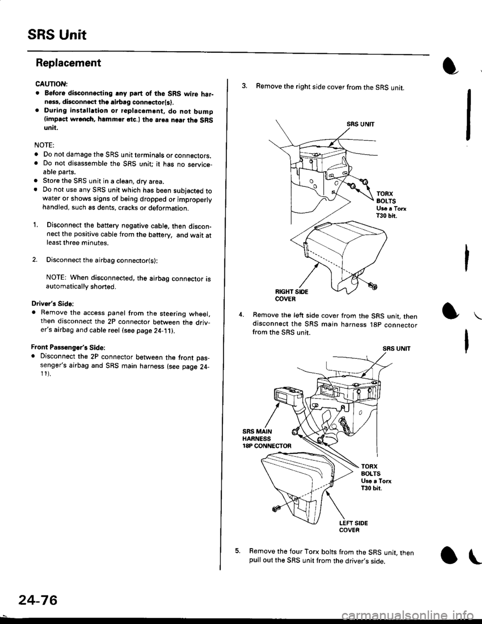
3. Remove the right side cover from the SRS unit.
SRS UNTT
TOBXBOLTSUge a TorxT30 bit.
RIGHT SIOE
Remove the left side cover from the SRS unit, thendisconnect the SRS main harness lgp connectorfrom the SBS unit.
SRS UNIT
5. Remove the four Torx bolts from the SRS unit, thenpull out the SRS unit from the driver,s side,
COVER
Page 1819 of 2189
How To Use This Manual
Circuit Schematics
oa
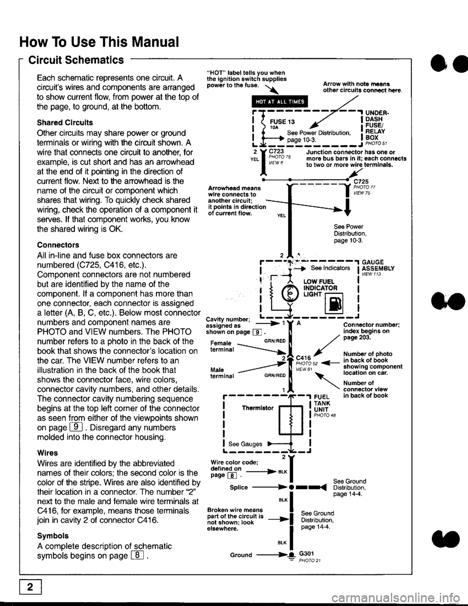
Each schematic represents one circult. A
circuit's wires and components are arranged
to show current flow, from power at the top of
the page, to ground, at the bottom.
Shared Circuits
Other circuits may share power or ground
terminals or wiring with the circuit shown. A
wire that connects one circuit to another, for
example, is cut short and has an arrowhead
at the end of it pointing in the direction of
current flow. Nelit to the anowhead is the
name o{ the circuil or comoonent which
shares that wiring. To quickly check shared
wiring, check the operation of a component it
serves. lf that component works, you know
the shared wiring is OK.
Connectors
All in-line and fuse box connectors are
numbered (C725, C416, etc.).
Component connectors are not numbered
but are identiJied by the name of the
component. lf a componenl has more than
one connector, each connector is assigned
a letter (A, B, C, etc.). Below most connector
numbers and comDonent names are
PHOTO and VIEW numbers. The PHOTO
number refers to a Dhoto in the back of the
book that shows lhe conneclor's location on
the car. The VIEW number refers to an
illustration in the back of the book that
shows the connector face, wire colors,
connector cavity numbers, and other details.
The connector cavity numbering sequence
begins at the top left corner oJ the connector
as seen from either of the viewooints shown
on page ffl . Disregard any numbers
molded into the connector housino.
Wires
Wires are identilied by the abbreviated
names of their colors; the second color rs the
color of the stripe. Wires are also identified by
their location in a connector. The number '2"
next to the male and female wire terminals at
C416, for example, means those terminals
join in cavity 2 of connector C416.
Symbols
A complete description of schematic
symbols begins on page | 8
"HOT" label tells you whenthe ignition switch suppliespower to the fuse. \
Artowhead meanswire connects toanother circuit;
Arrow with note rErngother circuils conncct h€re.
it .a
llu":: ^,{ ii t See Power Distribution, .I t----t oaqe tO-3. IL*--:--------J2 Y C723 Junction connectorYEL I Pao'o'8 more bus bars in it;
I - " " to two or more wire
l,/
-t>?
See PowerDistribution,page 10-3.
UNDER.DASHFUSE/RELAYBOX
has one oleach connactgterminala.
it ooints in directionof current flow.
TheImletor
t_I
Cavity number; L ---
Jiili'iJi!--' -----> '
shoin on page S .
Maleterminal
L?*?l?,-
"'"'I
c725
vlEUt/ 75
Connector number;index begins onpage 203.
Number ot photoin back ol bookshowing componentlocation on cat.
Number ofconneclor viewin back of book
7
GBN/FEO
See Ground
Soe Indicators I ASSEMBLY
:-------J
LOW FUELINDICATOFLIGHT r-l
EI
A
"o'r"/PHOTO 52 <-
\
FUELTANKUNIT
Splice ---------) O rr
".* I Page 14'4'
IBroken wire means | --^ -
iar";J.'It,;,rJ;ii; -----i Bffi,Bili*l
elsewhere. I 0a0e tn-a
IBrK Icround --->lL c301: ptioro 21
Page 1823 of 2189
How To Use This Manual
Component Locations
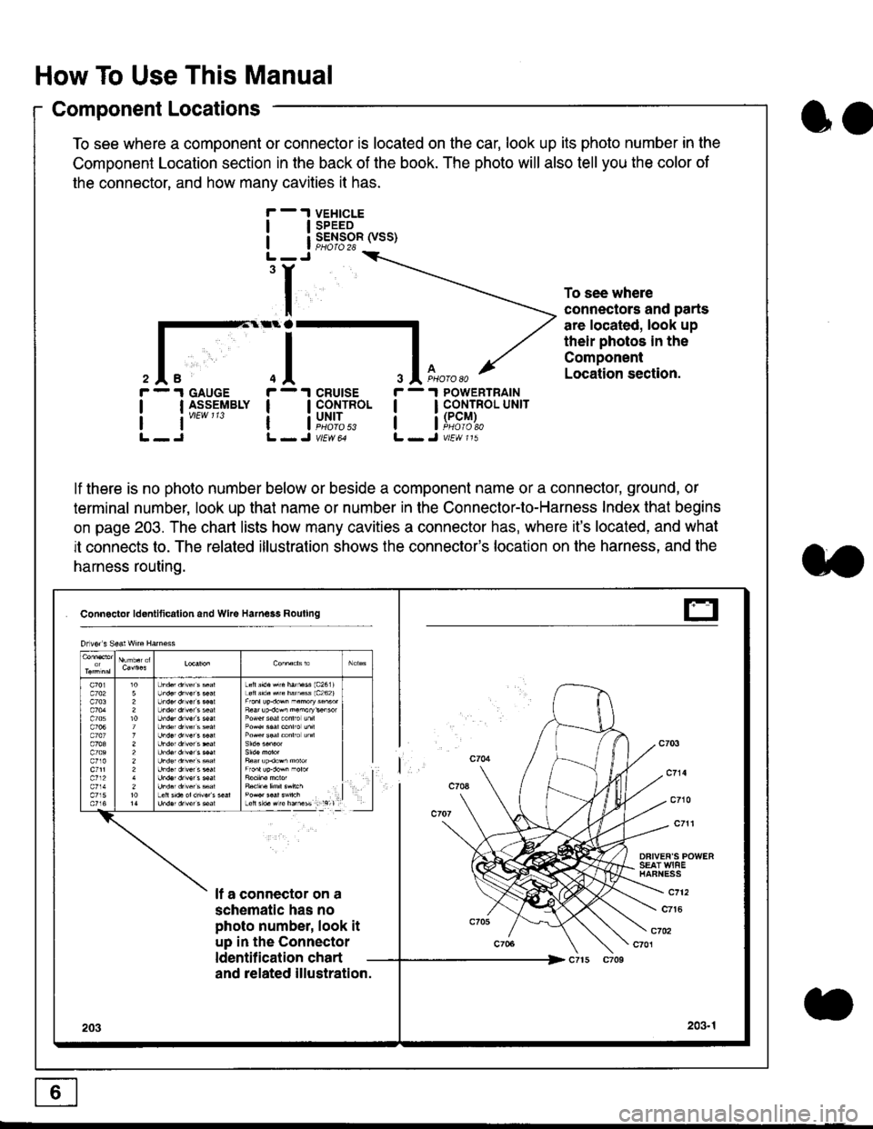
To see where a component or connector is located on the car, look up its photo number in the
Component Location section in the back of the book. The photo will also tell you the color of
the connector, and how many cavities it has.
To see where
connectors and parts
are located, look up
their photos in the
Component
Location section.
I
I
3
r - 1 GAUGE
| | I_S-9_EIBLY
lt''""'
r - 1 cRUtsE
! !fi':*
r - 1 POWERTRAIN
I I CONTROL UNrr
a i[i9#r,
lf there is no photo number below or beside a component name or a connector, ground, or
terminal number, look up that name or number in the Connector-to-Harness Index that begins
on page 203. The chart lists how many cavities a connector has, where it's located, and what
it connects to. The related illustration shows the connector's location on the harness, and the
harness routing.
Connactor ldontlticallon and Wke Harness Rouling
DFIVEF'S POWERSEAT WIAEHAFNESS
It a connector on a
schematic has no
photo number, look it
up in the Connector
ldentilication chart
c712
c7t6
c702c701
and related illustration.
203203.1
Drlvor s Sea! wne Harn€ss
Lefts'd.Hrc hatu$ 1c2611Loft s'd. src hamass 1c262)
F6ar up.dow^ n.morykisor
l
E
oo
Page 1824 of 2189
Connector Views
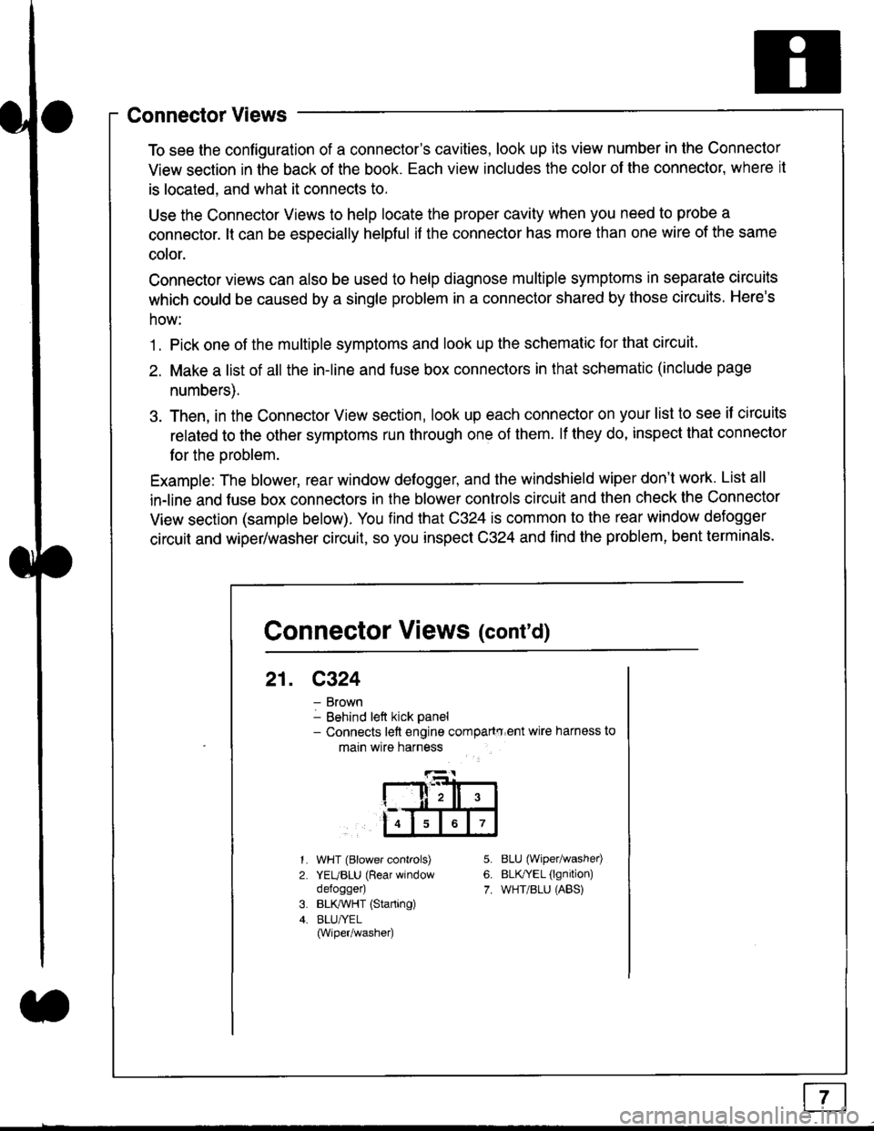
To see the configuration of a connector's cavities, look up its view number in the Connector
View section in the back of the book. Each view includes the color of the connector, where it
is located, and what it connects to.
Use the Connector Views to help locate the proper cavity when you need to probe a
connector. lt can be especially helpful if the connector has more than one wire of the same
cotor.
Connector views can also be used to help diagnose multiple symptoms in separate circuits
which could be caused by a single problem in a connector shared by those circuits. Here's
how:
1. Pick one of the multiple symptoms and look up the schematic for that circuit.
2. Make a list of all the in-line and fuse box connectors in that schematic (include page
numbers).
3. Then, in the Connector View section, look up each connector on your list to see il circuits
related to the other symptoms run through one of them. lf they do, inspect that connector
for the oroblem.
Example: The blower, rear window defogger, and the windshield wiper don't work. List all
in-line and fuse box connectors in the blower controls circuit and then check the Connector
View section (sample below). You find that C324 is common to the rear window defogger
circuit and wiper/washer circuit, so you inspect C324 and find the problem, bent terminals.
5.
6.
7.
1.
2.
WHT (Blower controls)
YEUBLU (Rear window
defogger)
BLK,ryVHT (Starting)
BLU/YEL(Wiper/washe0
8LU (Wiper/washed
BLfiEL (lgnition)
WHT/BLU (ABS)
Connector Views (cont'd)
21. C324
Brown
Behind left kick panel- Connects left engine compartry'ent wire harness to
main wire harness
ll,ll,
567
Page 1826 of 2189
Connectors - "C"
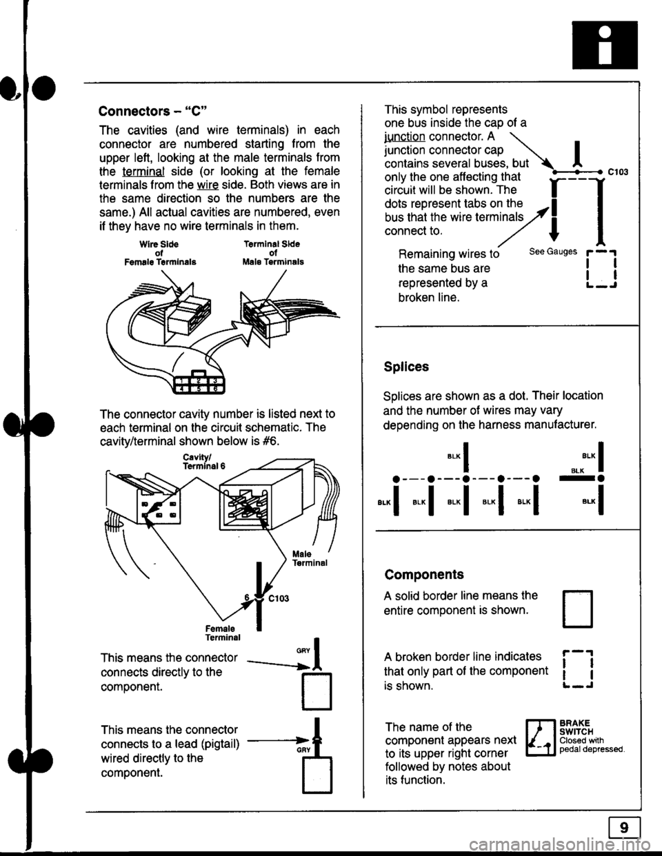
The cavities (and wire terminals) in each
connector are numbered starting from the
upper left, looking at the male terminals trom
the terminal side (or looking at the female
lerminals f rom the wire side. Both views are in
the same direction so the numbers are the
same.) All actual cavities are numbered, even
if they have no wire terminals in them.
Terminal SldeolMale Tsrminals
{
T
_A
Wlre SldeotFemalg Trrmlnala
The connector cavity number is listed next to
each terminal on the circuit schematic. The
cavity/terminal shown below is #6.
Terminal
This means the connector
connects directly to the
componenr.
This means the connector
connects to a lead (pigtail)
wired directly to the
component.
Cavlty/Termlnsl 6
only the one affecting that
ciriuit will be shown. The f
--f
!!*!"*F"#fi5'�;,Hy4
I
Remaining wires to
the same bus are
represented by a
broken line.
The name of the
component appears next
to its upper right corner
followed by notes about
its function.
This symbol represents
one bus inside the cao of a
iunction connector. A \
lr"ctb. connectorcap |contains several buses, but Ac103
tl
tl
*-
I ",.-"* I
a---a---a--- a--- o -a
*"1 *-l *-l *-l *"1 *-l
See Gauges
Splices
Solices are shown as a dot. Their location
and the number of wires may vary
depending on the harness manufacturer.
Components
A solid border line means the
entire component is shown.
A broken border line indicales
that only part of the component
is shown.
t_J
ll
ll
BRAXEswtTcHClosed wilhpedaldepressed.
Page 1829 of 2189
In the "OHMS" range, the DVOM will measure
resistance between two points along a circuit.
Low resistance means good continuity.
Diodes and solid-state devices in a circuit can
make a DVOM give a false reading. To check
a reading, reverse the leads, and take a
second reading. lf the readings differ, the
component is affecting lhe measurement.
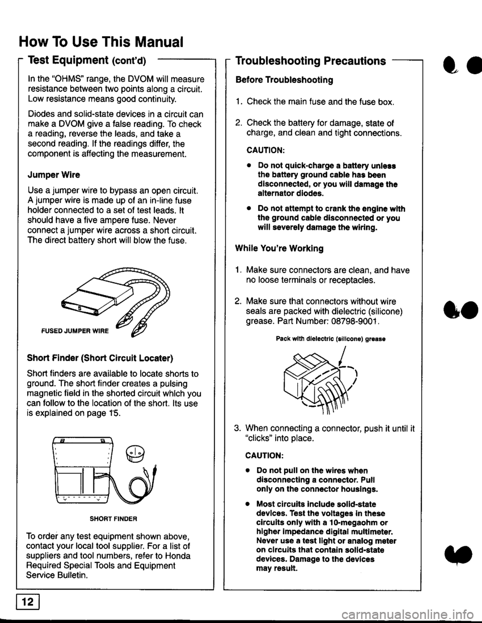
Jumper Wire
Use a jumper wire to bypass an open circuit.
A iumper wire is made up ot an in-line fuse
holder connected to a set of test leads. lt
should have a five amoere fuse. Never
connect a jumper wire across a short circuit.
The direct battery short will blow the fuse.
Short Finder (Short Circuit Locater)
Short finders are available to locale shorts to
ground. The short tinder creates a pulsing
magnetic field in the shorted circuit whlch you
can follow to the location of the short. lts use
is explained on page 15.
SHORT FINDER
To ordei any test equipment shown above,
contact your local tool supplier. For a list of
suppliers and tool numbers, refer to Honda
Required Special Tools and Equipment
Service Bulletin.
How To Use This Manual
Test Equipment (cont'd)
oa
Troubleshooting Precautions
Before Troubleshooting
1. Check the main fuse and the fuse box.
2. Check the battery for damage, state of
charge, and clean and tight connections.
CAUTION:
. Do not quick-charge a battery unlers
the battery ground cable has been
disconnected, or you will damage the
alternator diodes.
. Do not attempt to crank the engine wlth
the ground cable disconnected or you
will severely damage the wiring.
While You're Working
1. Make sure connectors are clean, and have
no loose terminals or receptacles.
2. Make sure lhat connectors without wire
seals are packed with dielectric (silicone)
grease. Part Number: 08798-9001 .
Pack wllh dlelectrlc (sillcons) greass
When connecting a connector, push it until it"clicks" into place.
Do not pull on the wires when
disconnecting a connector. Pull
only on the connector houslngs.
Most circuits Include solid-state
devlces. Test the voltages In these
circuits only with a lo-megaohm or
higher impedance digital multlm6ter.
Never use a test light or analog meter
on chcuits that contain solld-state
devices. Damage to the devices
may result.
oo
Page 1831 of 2189
How To Use This Manual
Troubleshooting Tests
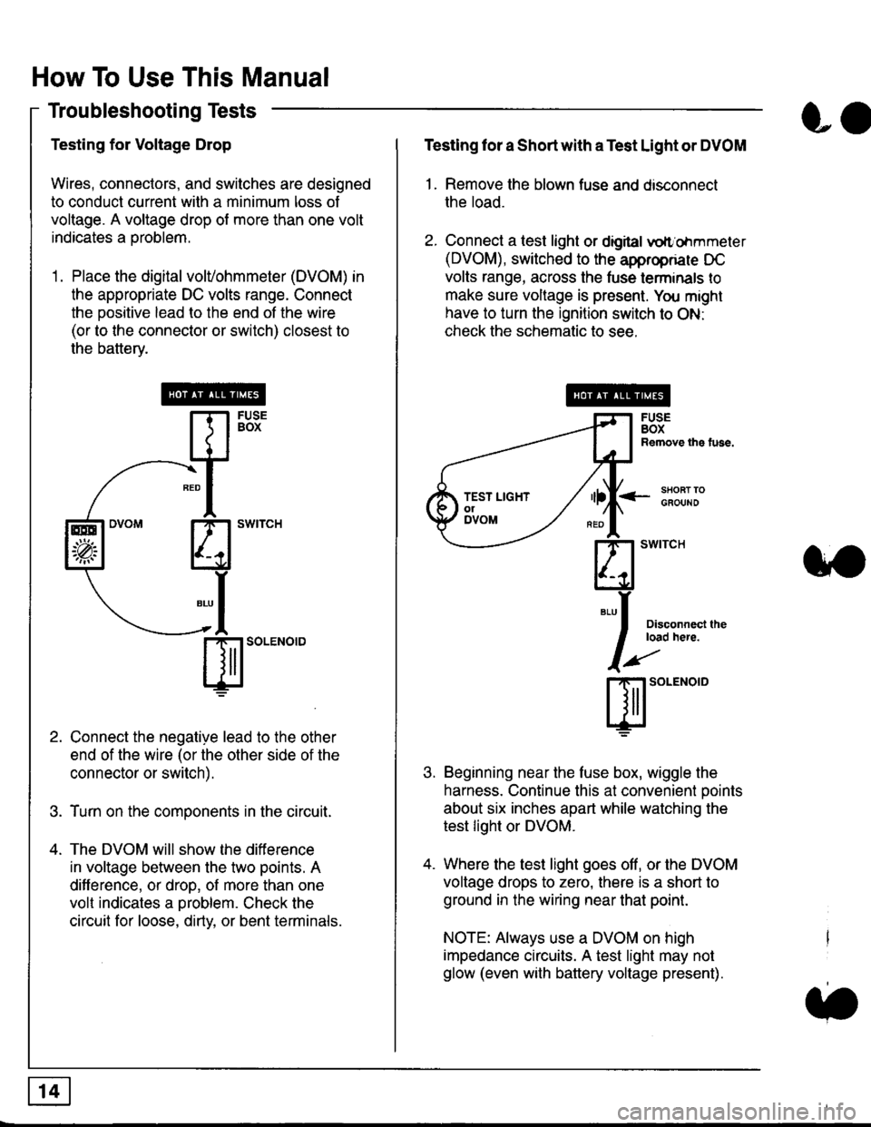
Testing for Voltage Drop
Wires, connectors, and switches are designed
to conduct current wilh a minimum loss of
voltage. A voltage drop of more than one volt
indicates a Droblem.
'1. Place the digital volVohmmeter (DVOM) in
the appropriate DC volts range. Connect
the positive lead to the end of the wire
(or to the connector or switch) closest to
the bafterv.
Connect the negative lead to the other
end of the wire (or the other side of the
connector or switch).
Turn on the components in the circuit.
The DVOM will show the difference
in voltage between the two points. A
difference, or drop, of more than one
volt indicates a oroblem. Check the
circuit for loose, dirty, or bent terminals.
co
Testing lor a Short with a Test Light or DVOM
1. Remove the blown fuse and disconnect
the load.
2. Connect a test light or digital
oltr'ohmmeter
(DVOM), switched to the appropnare DC
volts range, across the tuse lerminals to
make sure voltage is present. You might
have to turn the ignition switch to ON:
check the schematic to see.
<-s80RT TOGFOUNO
Disconnecl lheload here.
Beginning near the luse box, wiggle the
harness. Continue this at convenient ooints
about six inches apart while watching the
test light or DVOM.
Where the test light goes off, or the DVOM
voltage drops to zero, there is a short to
ground in the wiring near that point.
NOTE: Always use a DVOM on high
impedance circuits. A test light may not
glow (even with battery voltage present).
3'�'
ffito.'"o'o
.t.
TEST LIGHTolDVOM
Page 1833 of 2189
How To Use This Manual
Troubleshooting Tests (cont'd)
4. Turn on the short finder. This creates a
pulsing magnetic field around the wiring
between the fuse box and the short.
5. Beginning at the fuse box, slowly move
the short finder along the circuit wiring.
The meter will show current Dulses
through sheet metal and body trim. As
long as the meter is between the fuse and
lhe short, the needle will move with each
current pulse. Once you move the meter
past the point of the short, the needle will
stop moving. Check the wiring and
connectors in this area to locate the cause
of the short.
co