Page 1148 of 2189

Rear Suspension
Hub Bearing Unit Replacement (cont'dl
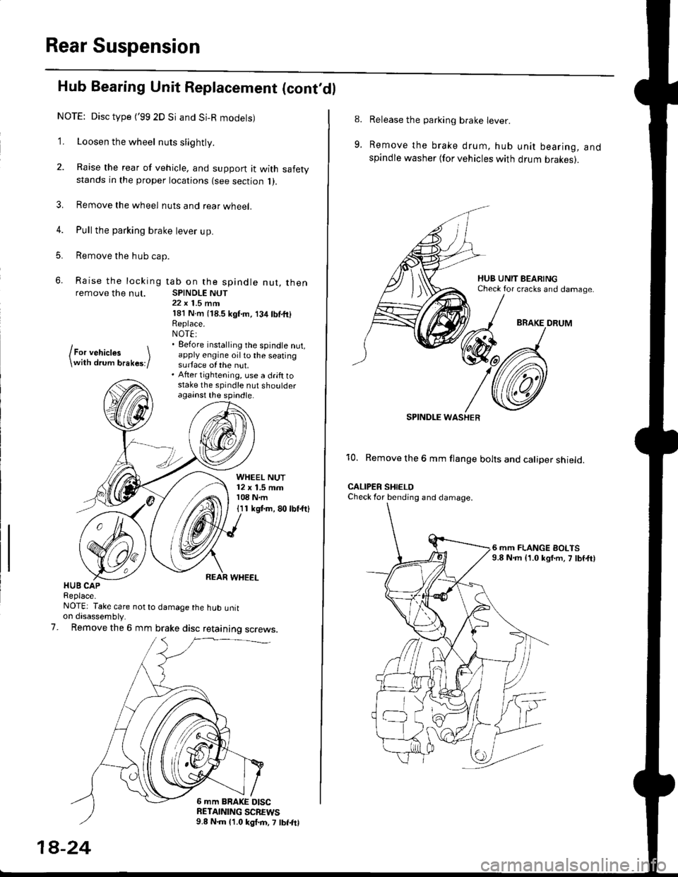
NOTE: Disc type {'99 2D Si and Si-R modets)
1. Loosen the wheel nuts slightly.
2. Raise the rear of vehicle, and support it with safetystands in the proper locations {see section 1).
3. Remove the wheel nuts and rear wheel.
4. Pull the parking brake lever up.
5. Remove the hub cap.
6. Raise the locking tab on the spindle nut, thenremove the nut. SPINDLE NUT22 x 1.5 mrn181 N.m (18.5 kgf'm, 134lbf.fi)Replace.NOT€:. Eefore installing the spindle nut,apply engine oil to the seatingsurface of the nut.. After tightening, use a drift tostake the spindle nut shoulderagainst the spindle.
lFor vehictes \\with drum brakes;/
WHEEL NUT12 x 1.5 mm108 N.m
I I 1 kgt m, 80 lbf.ftl
HUB CAPReplace-NOTE: Take care not to damage the hub untton disassembly.
Remove the 6 mm brake disc retaining screws.7.
6 mm BRAKE DISCRETAINING SCBEWS9.8 N.m 11.0 kgl.m, 7 lbf.frl
1A-24
8.
9.
Release the parking brake lever.
Remove the brake drum, hub unit bearing, andspindle washer lfor vehicles with drum brakes).
BRAKE DRUM
SPINDI-E WASHER
10. Remove the 6 mm flange bolts and caliper shield.
CALIPER SHIELOCheck for bending and damage.
6 mm FLANGE BOLTS9.8 N.m {1.0 kgf.m, 7 lbf,ft)
Page 1149 of 2189

T
11.
1)
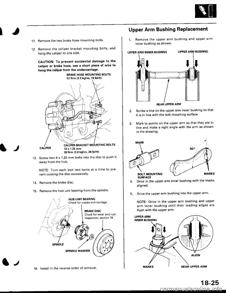
Remove the two brake hose mounting bolts
Remove the caliper b.acket mounting bolts, and
hang the caliPer to one side
CAUTION: To prevent accidental damage to the
caliper or brake hose, use a short piece of wile to
hang the caliper from the undercarriage.
BRAKE HOSE MOUNTING BOLTS
22 N'm {2.2 kgf'm, 16lbt"ft}
CALIPER 10 x 1.25 mm38 N'm (3.9 kgf'm, 28 lbf'ftl
Screw two 8 x 1.25 mm bolts into the disc to push it
away from the hub.
NOTE: Turn each bolt two turns at a time to pre-
vent cocking the disc excessively.
Remove the brake disc.
Remove the hub unit bearing from the spindle
SPINOLE WAS}IER
lr
14.
15.
lt
16. lnstall in the reverse order of removal.
1A-25
Upper Arm Bushing RePlacement
1. Remove the upper arm bushing and upper arm
jnner bushing as shown
UPPER ARM INNER BUSHING UPPER ARM BUSHING
REAR UPPER ARM
Scribe a line on the upper arm inner bushing so that
it is in line with the bolt mounting surface
Mark to points on the upper arm so that they are In
line and make a right angle with the arm as shown
in the drawing.
BOLT MOUNTINGSURFACE
Drive in the upper arm inner bushing with the marks
aligned.
Drive the upper arm bushing into the upper arm
NOTE: Drive in the upper arm bushing and upper
arm inner bushing until their leading edges are
flush with the uPPer arm
ttI
5.
UPPER ARM
Page 1186 of 2189

Rear Brake Caliper
Reassembly (cont'dl
L
PARKING NUT28 N.m (2.8 kgt m,20 rbr.trt
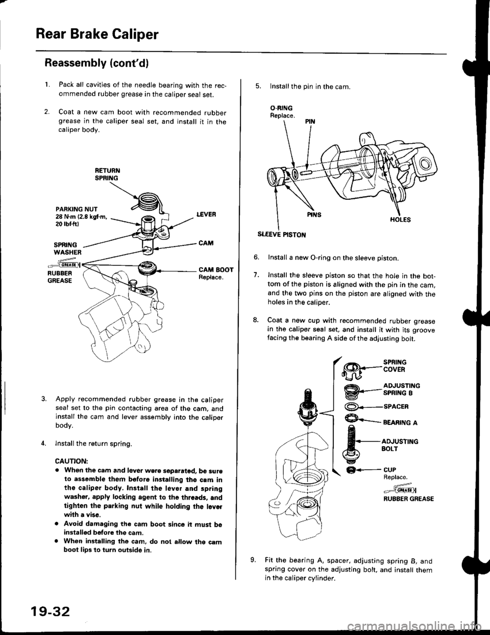
Pack all cavities of the needle bearing with the rec,
ommended rubber grease in the caliper seal set,
Coat a new cam boot with recommended rubbergrease in the caliper seal set, and install it in thecaliper body.
SPRII{GWASHEN
z..-_e!!!9!.{RUBBERGREASE
Apply recommended rubber grease in the caliperseal set to the pin contacting area of the cam, andinstall the cam and lever assembly into the caliperbodv.
lnstall the return spring.
CAUTION:
. When the cam and lever wgre separatod. b€ surgto assemble them bofore installing the cam inthe caliper body, Install the lev€r and spring
washer. apply locking agent to the threads, andtighten the parking nut while holding the l.vorwhh a vise,
. Avoid damaging the cam boot since it must bsinstalled before thg cam.. When installing the cam, do nol allow the camboot lips lo turn outside in.
19-32
5. Installthe pin in the cam.
O.RINGReplace.
SLEEVE PISTON
Install a new O-ring on the sleeve pisron.
Install the sleeve piston so that the hole in the bot-tom of the piston is aligned with the pin in the cam,and the two pins on the piston are aligned with theholes in the calioer.
Coat a new cup with recommended rubber grease
in the caliper seal set, and install it with its groove
facing the bearing A side of the adjusting bolt.
7.
€8.--:BTif
@'-.-3nfi""'i"
@--seacrn
$ eeenrne a
fi,*,*^"
GF-
Fit the bearing A, spacer. adjusting spring B, andspring cover on the adjusting bolt, and install themin the caliDer cvlinder.
CUPReplace.
=^.#-g!!!!!Jl
RUBBER GREASE
o
Page 1190 of 2189
Rear Drum Brake
Inspection
1.
4.
Check the wheel cylinder for leakage.
Check the brake linings for cracking, glazing, wear,
and contamination.
Measure the brake lining thickness.
Brake Lining Thickness:
Standard: 4.0 mm {0.157 in}
Service Limit: 2.0 mm 10.08 in)
NOTE; Measurement does not include brake shoe
thickness.
lf the brake lining thickness is less than the service
limit, replace the brake shoes as a set.
Check the bearings in the hub unit for smooth oper-
ation. lf defective, refer to section 18
WHEEL CYLINDER
LININGS
19-36
6. Measure the inside diameter oJ the brake drum
using the inside vernier calipers.
Drum Inside Diameter:
Standard: 199.9 - 200.0 mm {7.870 - 7.874 in)
Servic€ Limit: 201.0 mm (7.913 inl
lf the inside diameter of the brake drum is more
than the service limit, replace the brake drum.
Check the brake drum for scoring, grooves, and
cracks.
7.
8.
INSIDE VERNIER CALIPERS
BRAKE ORUM
Page 1230 of 2189
l}tWheel Sensor Replacement
NOTE:
. Becareful when installingthe sensors to avoid twisting the wires.
. The torque value of the bolts is 9.8 N.m (1.0 kgf.m, 7 lbf.ft).
Front
FRONT WHEEL SENSOR
Rear
1. Remove the hub bearing unit (see section 18).
2. Remove the four backing plate bolts.
3, Pull the backing plate away from the trailing arm, then remove the wheel sensor. lt is not necessary to disconnect the
brake line.
NOTE: This illustration is drum brake type. The torque value of the disk type is same as drum type.
REAR WHEEL SENSOR
J\
It
19-77
Page 1281 of 2189

Troubleshooting
SymptomProbable Cause
Water leaks1. Clogged drain tube.
2. Gap between glass weatherstrjp and roof panel.
3. Defective or improperly installed glass weatherstrip.
4. Gap between drain seal and roof panel.
Wind noise'1. Excessive clearance between glass weatherstrip and roof panel.
Motor noise1. Loose motor.
2. Worn gear or bearing.
3. Cable assembly deformed.
Glass does not move, but motor turns'1. Clutch out of adjustment.
2. Foreign matter stuck between guide rail and slider.
3. lnner cable loose.
4. Cable assembly not attached properly.
Glass does not move and motor does not turn
{glass can be moved with moonroof wrench)
1. Blown fuse,
2. Faulty switch.
3. Battery run down.
4. Defective motor.
5. Faulty relay.
D
Glass Height Adjustment
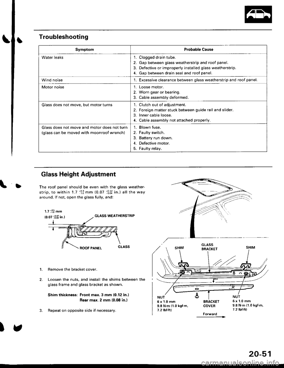
The roof panel should be even with the glass weather-
strip, to within 1.7 :lr3 mm (0.07 :3:31 in.) all the way
around. lf not, open the giass fully, and:
GLASS WEATHERSTRIP
1. Remove the bracket cover.
Loosen the nuts, and install the shims between the
glass frame and glass bracket as shown.
Shim thickness: Front max.3 mm 10,12 in.l
Rear max. 2 mm 10.08 in.)
Repeat on opposite side i{ necessary.
)
5x1.0mm9.8 N.m 11.0 kgf m,7.2 rbtft)
SRACKETCOVEB
----------1>
6x1.0mm9.8 N.m {1.0 kgtm,7.2 tbf.ft)
1.7 tl.8 mm
{0.07 :3 3i in.}
20-51
Page 1582 of 2189
Charging System
Component Location Index
UNDER.HOOD FUSE/RELAY BOX/*Has replaceable ELECTRICAL LOAD II DETECTOR (ELD) UNIT '
Troubleshooting, page 23-1 14Replacement, page 23-120Bectifier Removal, page 23,121Rectifier Test, page 23-122Rear Bearing Replacement, page 23-j24
*ELD unit: USA
CHARGING SYSTEM LIGHT(ln the gauge assembly)Test, page 23- l14
BATTERYTest, page 23-91
ALTERNATOR BELTInspection and Adjustment, page 23-t25
[]
23-112
Page 1591 of 2189
JRectifier Removal
1. Remove the four through bolts.
Heat the rear bearing seat with a 1,000 W hair drier
tor about five minutes (120 - 140'F, 50 - 60"C).
3. Separate the rear housing from the drive-end hous-
ing by inserting a flst tip screwdriver into the open-
ings and prying them a part. Be careful not to dam-
age the stator with the tip of the screwdraver.
Seoarate the rear housing and drive-end housing
with the stator attached to the rear housing.
DEIVE-END HOUSING
STATOR
{cont'd)
23-121
REAR HOUSING