Page 1291 of 2189
Il
2Di
>: Clip locationsa>,28>,3
CLIP
G>,4H >,2
D >,3>i Screw location3.4
REAR SHELF
SIOE TRIM PANELRemove the rear seat-back andrear seat cushaon (see page20-a1l.
,
Disconnect the highmount brake light
SEAT BELT
€'
/>"RIGHT KICKPANEL
)
TRIM
nJ'.'rI\ZI
1\f-
F>,8
N 4'dr
SIDE TRIM
LOWER ANCHOR(see page 20-86)
c>, 14E>,2
Installation is the reverse of the removal procedure.
NOTE:
. lf necessary, replace any damaged clips.
. Before installing the anchor bolts and rear shelf,
make sure there are no twists or kinks in the seat
belts.
FRONT PILLAR
FRONT SEATBELT UPPERANCHOR
v
.h,'t6d
\
LEFT KICKPANEL
20-61
Page 1294 of 2189
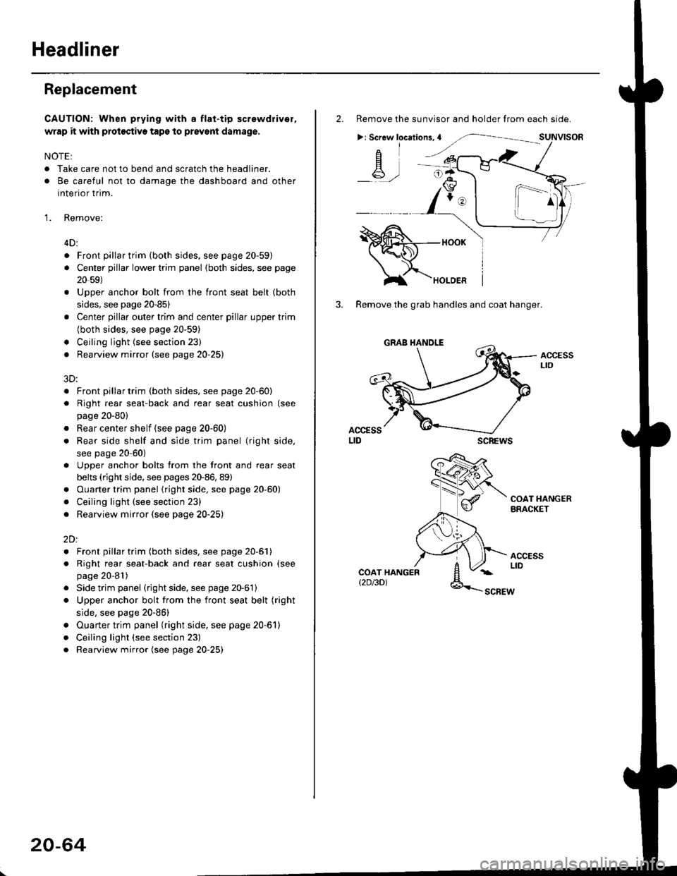
Headliner
Replacement
CAUTION: When prying with a flat-tip screwdriver,
wrap it with proioctiva tap€ to prevsnt damage.
NOTE:
. Take care not to bend and scratch the headliner.
. Be careful not to damage the dashboard and other
interior trim.
'1. Remove:
4D:
. Front pillar trim (both sides. see page 20-59)
. Center pillar lower trim panel (both sides, see page
20 59)
Upper anchor bolt from the front seat belt (both
sides, see page 20-85)
Center pillar outer trim and center pillar upper trim
(both sides, see page 20-59)
Ceiling light (see section 23)
Rearview mirror (see page 20-25)
a
a
a
a
a
3D:
. Front pillar trim (both sides, see page 20-60)
. Right rear seat-back and rear seat cushion (see
page 20-80)
. Rear center shelf (see page 20-60)
. Rear side shelf and side trim panel (right side,
see page 20-60)
. Upper anchor bolts from the front and rear seat
belts (right side. see pages 20-86, 89)
. Ouarter trim panel (right side, see page 20-60)
. Ceiling light (see section 23)
. Rearview mirror (see page 20-25)
2Dl
. Front pillar trim (both sides, see page 20-51)
. Right rear seat-back and rear seat cushion (see
page 20-81)
Side trim panel (right side, see page 20-61)
Upper anchor bolt from the front seat belt (right
side, see page 20-86)
Ouarter trim panel (right side, see page 20-6'l)
Ceiling light (see section 23)
Rearview mirror (see page 20-25)
20-64
2. Remove the sunvisor and holder from each side.
>: Screw locations,4
-A-,-
3. Remove the grab handles and coat hanger.
scREws
ACCESSLto
COAT HANGERBRACKET
ACCESSLIDCOAT HANGERt2D/3DlSCBEW
1^
Page 1295 of 2189
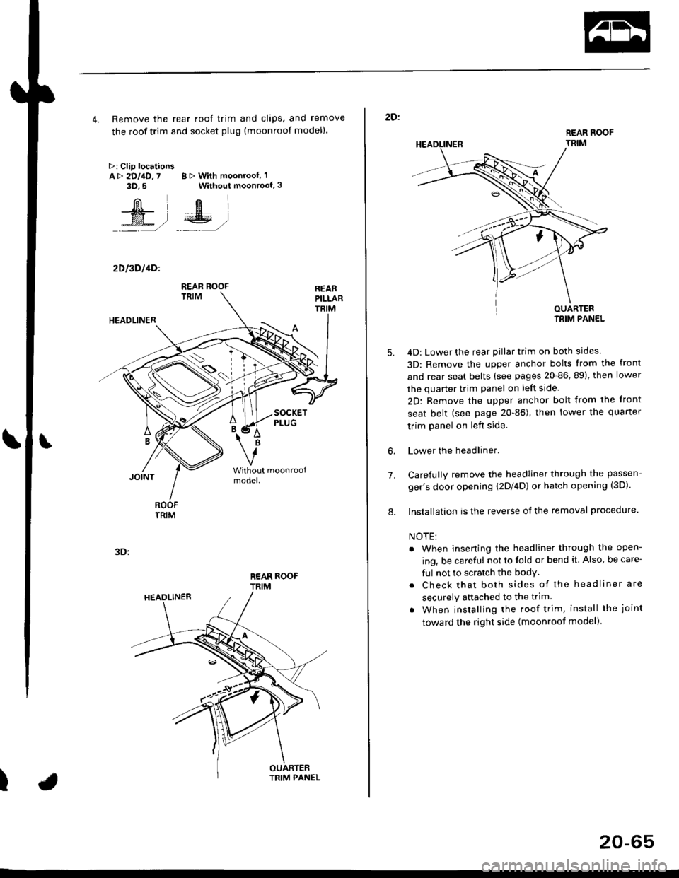
4. Remove the rear roof trim and clips, and remove
the roof trim and socket plug (moonroof model).
>: Clip locationsA> 2DllD,7 B > With moonroof, 'l
3D.5 Without moonroof,3
[il',fEl
t% .l €E .l':: =,/ _._- ,/
2D l3D l4Dl
REAR ROOFTRIM
3D:
t
REAR ROOF
TRIM
2D:
5.
7.
OUARTERIRIM PANEL
4D: Lower the rear pillar trim on both sides
3D: Remove the upper anchor bolts from the front
and rear seat belts (see pages 20-86, 89), then lower
the quarter trim panel on left side.
2D: Remove the upper anchor bolt from the front
seat belt (see page 20-86), then lower the quaner
trim panel on left side.
Lower the headliner.
Carefully remove the headliner through the passen-
ger's door opening (2Dl4D) or hatch opening (3D).
Installation is the reverse of the removal procedure.
NOTE:
. When inserting the headliner through the open-
ing, be careful not to fold or bend it. Also, be care-
ful not to scratch the bodY.
. Check that both sides of the headliner are
securely attached to the trim.
. When installing the roof trim, install the joint
toward the right side (moonroot model)
6.
8.
20-65
Page 1296 of 2189
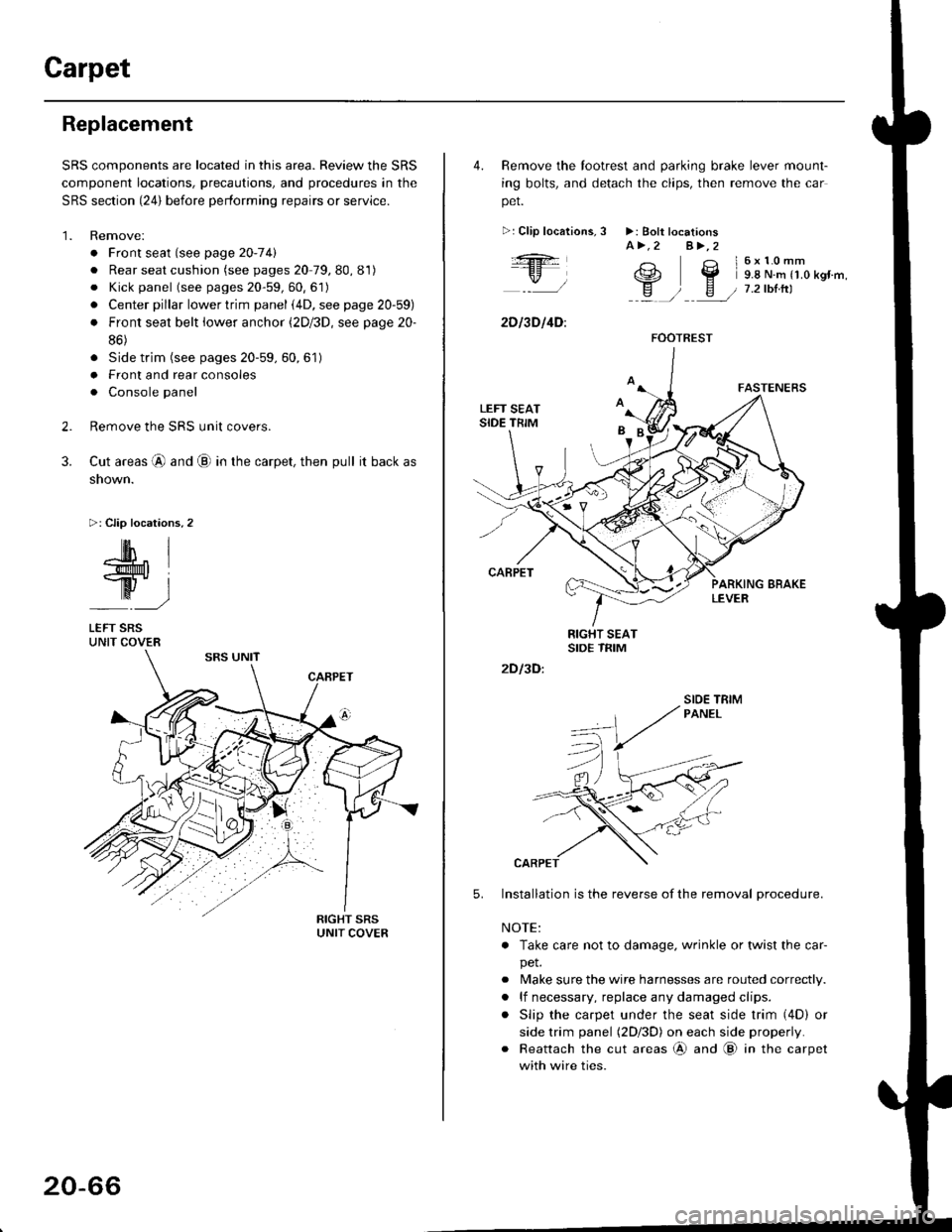
Carpet
Replacement
SRS components are located in this area. Review the SRS
component locations, precautions, and procedures in the
SRS section {24} before performing repairs or service.
1. Remove:
. Front seat (see page 2O-7 4l
. Rear seat cushion (see pages 20 79, 80, 81)
o Kick panel (see pages 20-59, 60, 61)
o Center pillar lowertrim panel i4D, see page 20-59)
. Front seat belt iower anchor (2Dl3D, see page 20-
86)
. Side trim (see pages 20-59, 60,61)
o Front and rear consoles
. Console panel
Remove the SRS unit covers.
Cut areas @ and @ in the carpet, then pull it back as
snown.
>: Clip locations,2
2.
3.
-lM- IlMt l
ry-l
LEFT SRSUNIT COVER
20-66
4. Remove the tootrest and parking brake lever mount-
ing bolts, and detach the clips, then remove the car
pet.
>:Clip localions,
:ft
\/l
2D l3D l4D:
3 >: Bolt locationsA>.2 A>,2
3 l6x10mm
e2 Y 9.8 N.m r1.o kgr'm,
H ) E / 7.2tbtrtl::a /
5.
2D I3D:
Installation is the reverse of the removal procedure.
NOTE:
. Take care not to damage. wrinkle or twist the car-
pet.
. Make sure the wire harnesses are routed correctly.
. lf necessary, replace any damaged clips.
. Slip the carpet under the seat side trim (4D) or
side trim panel (2Dl3D) on each side properly.
. Reattach the cut areas @ and @ in the carpet
with wire ties.
FOOTREST
SIOE TBIM
Page 1301 of 2189
Remove the following parts Irom the dashboard'
. Driver's dashboard side cover
o Passenger's dashboard lower cover
. Dashboard center lid
Disconnect the connectors and air mix control cable'
6x1.0mm9.8 N.m 11.0 kgl.m,
D>, 1
@7 2'orftl - ---//_._J
,{nil Lll , ,"o
Ift#5 L //Hl Wlj%u|5 i//Wt qT
W72-t11 7'::--J
>: Clip locationsA>, 1 B>, 1
Loosen the bolt.
DASHBOARD
AIR MIX CONTROL
CONNECTORS
FRONT PASSENGER'SAIRBAG CONNECTOR
Remove the bolts, then lift and remove the dashboard'
CAUTION: Use proteqtive plates on the bottom ot the front pillar trim'(cont'd)
20-71
M,::;:"lx3T:iJnif:3lilH:fl"*:1::f"*'il;ili"'"
disconnect rhe front passeneer's airbas
>: Bolt, screw locaiions
A>,7B>, 1
,i( 8x125mm(!,@ 22 N.m t2.2 kstm,-v, 16 tbf.ftl
8xl.25mm I22 N.m 12.2 kgt'm, I'"tt:___J
c>, 1
@
c>,6
Page 1315 of 2189
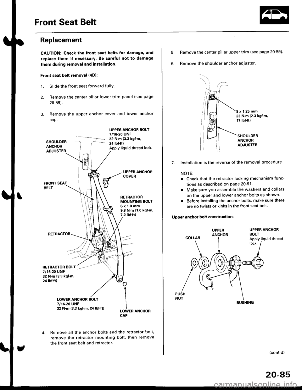
Front Seat Belt
Replacement
CAUTION: Check the front seat belts for damage, and
replace them it necessary. Be carolul not to damage
them during removal and installation.
Front seat belt removal (4Dl:
1.Slide the front seat forward fully.
Remove the center pillar lower trim panel (see page
20-59).
Remove the upper anchor cover and lower anchor
cap.
SHOULDERANCHOR
UPPER ANCHOR BOLT7/16-20 UNF32 N.m (3.3 kgit m,24 lbf.ft)Apply liquid thread lock.
2.
3.
FRONT SEATBELT
RETRACTOR
RETRACTORMOUNTING BOLT6x1.0mm9.8Nm(1.0kgf.m.7.2 tbf.ftl
ER ANCHOR
Remove all the anchor bolts and the retractor bolt,
remove the retractor mounting bolt, then remove
the front seat belt and retractor.
1
I
ILOWCAP
7/1&20 UNF32 N.m (3.3 kgl.m.24 rbl.ftl
7/16-20 UNF32 N.m {3.3 kgf.m,24lbf.ft}
6.
8 x 1.25 mm23 N.m {2.3 kgt'm,17 tbf.ft)
ANCHORADJUSTER
7. Installation is the reverse of the removal procedure
NOTE:
. Check that the retractor locking mechanism func-
tions as described on page 20-91.
. Make sure you assemble the washers and collars
on the uDDer and lower anchor bolts as shown.
. Before installing the anchor bolts, make sure there
are no twists or kinks in the front seat belt.
Upper anchor boh construciion:
UPPER ANCHORBOLT
Remove the center pillar upper trim (see page 20-59)
Remove the shoulder anchor adjuster.
UPPER
COLLARApply liquid thread
(cont'd)
20-85
SUSHING
Page 1338 of 2189
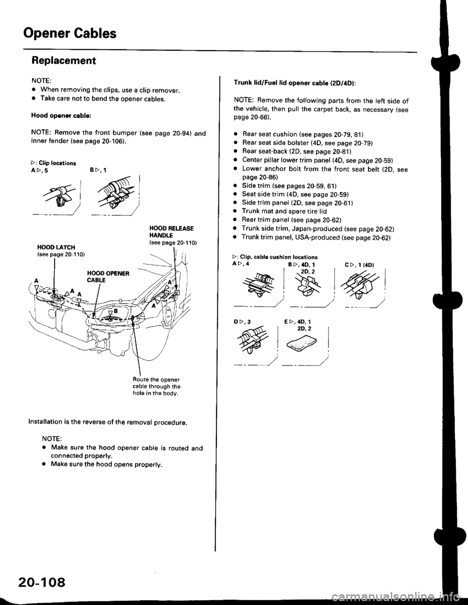
Opener Cables
Replacement
NOTE:
t When removing the clips. use a clip remover.. Take care not to bend the opener cables.
Hood op€ne. cable:
NOTE; Remove the front bumper (see page 20-94) andinner fender (see page 20-106).
>: Clip loc.tionsA >,5 B>, 1
ry)
g
HOOD REI.TASEHANDI.I(see page 20-110)
cable through thehote in th6 body.
Installation is the reverse of the removal procedure.
NOTE:
a Make sure the hood opener cable is routed andconnected properly.
. Make sure the hood opens properly.
20-10a
Tlunk lid/Fuel lid opener cabte (2Dl4D):
NOTE: Remove the following parts from rhe Ieft side ofthe vehicle, then pull the carpet back, as necessary {seepage 20-66).
. Rear seat cushion (see pages 20-79, 81). Rear seat side bolster (4D, see page 20,79). Rear seat-back (2D, see page 20-81). Center pillar lower trim panel (4D, seepage20-59)o Lower anchor bolt from the front seat belt {2D. seepage 20-86)
. Side trim (see pages 20-59, 61). Seat side trim (4D, see page 20-59). Side trim panel (2D, see page 20-61). Trunk mat and spare tire lid. Reartrim panel (see page 20-62). Trunk side trim, Japan-produced (see page 20-62). Trunk trim panel, USA-produced (see page 20-62)
>r Clip, cable cushion locationsA >,4 B >,4D_ 1c >, 1 l4D)2D,2
t@#lB
_ : _/ _-___)
E >,4D, 12D,2
@i
_ _,, -/
D>,3
Page 1450 of 2189
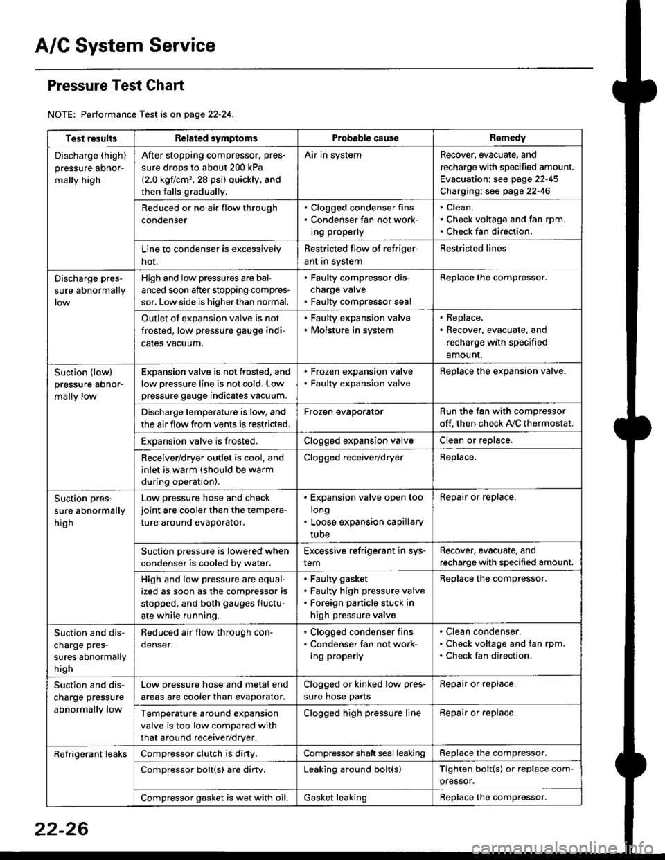
A/C System Service
Pressure Test Chart
NOTE: Performance Test is on page 22-24,
Test resultsRelated symptomsProbabl€ causeRemedy
Discharge (high)
pressure aDnor-
mally high
After stopping compressor. pres-
sure drops to about 200 kPa
{2.0 kgflcm,,28 psi) quickly, and
then falls gradually.
Air in systemRecover, evacuate, and
recharge with specified amount.
Evacuation: see page 22-45
Charging: see page 22-46
Reduced or no air flow through
condenser
. Clogged condenser fins. Condenser fan not work-
ing properly
Clean.
Check voltage and fan rpm.
Check fan direction.
Line to condenser is excessively
hot.
Restricted flow of refriger-
ant in system
Restricted lines
Discharge pres-
sure abnormally
High and low pressures are bal-
anced soon after stopping compres-
sor, Low side is higher than normal.
. Faulty compressor dis-
charge valve. Faulty compressor seal
Replace the compressor.
Outlet of expansion valve is not
frosted, low pressure gauge indi-
cales vacuum.
. Faulty expansion valve. Moisture in system
. Replace,. Recover, evacuate, and
recharge with specified
amount.
Suction (low)
pressure abnor-
mally low
Expansion valve is not frosted, and
low oressure line is not cold. Low
pressure gauge indicates vacuum.
. Frozen expansion valve. Faulty expansion valve
ReDlace the exoansion valve.
Discharge temperature is low. and
the air flow from vents is restricted.
Frozen evaporatorRun the fan with compressor
off. then check A,/C thermostat.
Exoansion valve is frosted.Clogged expansion valveClean or replace.
Receiver/dryer outlet is cool, and
inlet is warm (should be warm
during operation).
Clogged receiver/dryerReplace.
Suction pres-
sure abnormally
hig h
Low pressure hose and check
joint are cooler than the tempera-
ture around evaporator.
. Expansion valve open too
long. Loose expansion capillary
tube
Repair or replace.
Suction oressure is lowered when
condenser is cooled bv water.
Excessive refrigerant in sys-
tem
Recover. evacuate, and
recharge with specified amount.
High and low pressure are equal-
ized as soon as the compressor is
stopped, and both gauges fluctu-
ate while running.
Faulty gasket
Faulty high pressure valve
Foreign particle stuck in
high pressure valve
Replace the compressor.
Suction and dis-
charge pres-
sures abnormally
h igh
Reduced air flow through con-
denser.
. Clogged condenser fins. Condenser fan not work-
ing properly
Clean condenser.
Check voltage and fan rpm.
Check fan direction.
Suction and dis-
charge pressure
abnormally low
Low pressure hose and metal end
areas are cooler than evaporator.
Clogged or kinked low pres-
sure hose parts
Repair or replace.
Temperature around expansion
valve is too low compared with
that around receiver/dryer.
Clogged high pressure lineRepair or replace.
Refrigerant leaksCompressor clutch is diny,Compressor shaft seal leakingReplace the compressor.
Compressor bolt{s) are diny.Leaking around bolt(s)Tighten bolt(s) or replace com-
pressor.
Compressor gasket is wet with oil.Gasket leakingReplace the compressor.
22-26