Page 105 of 2189
39. Remove the left and right front mount and bracket'
MOUNT/BRACKET
40. Remove the rear mount bracket.
41. Remove the uPPsr bracket.
42. Remove the transmission mount bracket, then
remove the transmission mount.
44.
Check that the engine/transmission is completely
free of vacuum hoses, fuel and coolant hoses and
electricalwiring.
Slowly raise the engine approximately 150 mm (6 in)'
Check once again that all hoses and wires are discon-
nected from the engine^ransmission
Raise the engine all the way, and remove it from the
car.
UPPER
TRANSMISSION
45.
5-11
Page 106 of 2189
Engine RemovaUlnstallation
Installation
Brackei Bolts Torque Specifications:
Dl5Y5, Dl6Y7, Dl6Y8 €nginss
D16Y5, D16Y8 engines (M/Tl:
REAR STIFFENER
8 x 1.25 mm2/t N.m 12.4 kgf.m, 17 tbf.ftl
EXCEPT D16Y5, Dl6Yg engines lM/T)jSTIFFENERTighten the bolts on the stiffenerin the numbered sequence as shown
10 x 1.25 mm44 N.m 14.5 kgf.m,33 tbf.frt
O8x1.25mm24 N.m {2.4 kg{.m,17 tbr.ftt
10 x 1.25 mm14 N.m 14.5 kgt m,33 tbf.ft)
10 x 1.25 mm44 N.m {4.5 kgt m,33 tbr.ftl
10 x 1.25 mm54 N.m {5.5 kgf.m,40 rbf.ftl
10 x 1.25 mm44 N.m {4.5 kg'f.m,33 tbtftlALTERNATOFBRACKET
li) o).
l3l 10 x 1.25 mm44 N.m {1.5 kgt.m,33 tbt.ft)8 x 1.25 mm24 N.m (2.4 kgf.m,17 tbf.ft)
o16Ys, D16Y8enginoslM/T):FRONTSTIFFENER
10 x 1.25 mm4,4 N.m {4.5 kg{.m.33 tbf.ftl8 x 1.25 mm2{ N.m (2.t kgtm,17 rbtft)
10 x 1.25 mm14 N.m (4.5 kgf.m,33 lbf.ftl
5-12
Page 107 of 2189
816A2 engine
P/S PUMPBRACKET
REARSTIFFENER
SIDE ENGINEMOUNT BRACKET
t0 x 1.25 mmia{ N.m (i1.5 kgt rn,
33 lbt.tr)
t
12 x 1.25 nm57 N.m {5.8 kgf,m,12 tbl.ttl
8 x 1.25 mm24 N.m (2.4 kgl.m,17lbf.ft)
FRONTSTIFFENER
A/C COMPBESSORBRACKET
10 x 1.25 mm54 N m {5.5 kgf m, a0 lbl ft}
10 x 1.25 mm4a N,m (4.5 kgf.m,33 tbf.ftt
ALTERNATORBRACKET
'12 x 1.25 mm
57 N.m {5.8 kgt'm,
42 tbt.ft)8 x 1.25 mm24 N.m {2.4 kgf.m,17 tbtft)
'10 x 1.25 mm,14 N.m {,1.5 kgt.m,33 rbf.ft)
(cont'd)
5-13
Page 109 of 2189
3. Install the rear mount bracket, then tighten the bolts
in the numbered sequence shown (O - @).
CVT:
O 12 x 1.25 mm59 N.m (6.0 kgl'm,ilil lbf ftlReplace.
12 x 1.25 mm59 N.m 16.0 kgf'm,|:r tbf.tt)Replace.
O 12 x 1.25 mm59 N'm {6.0 kgf'm,/€ lbf.ftlReplace.
Except CVT:
,@ 14 x'1.5 mm
/ 8:t N.m {8.5 kgf.m,
/ 61 rbr.fr) Replace.
O 12 r 1.25 mm
59 N m 16.0 kgt m,(} tbf.fttReplace.
Olax1.5mm83 N.m 18.5 kgf.m,61 tbf.ftlReplace.
L
4. Tighten the bolvnuts on the transmission mount
bracket in the numbe.ed sequence shown (O - O).
@ t2 x t.2s mm7,1N.m (7.5 kg{ m, 54 lbf ftl
Tighten the bolts on the right front mounvbracket in
the numbered sequence shown (O - @).
GW:
O to x 1.25 mm54 N.m {5.5 kgl.m./|{} lbf.ftl
10 x 1.25 mm4,1 N.m {4.5 kgf.m. 33 lbf.ftl
(cont'd)
5-15
12 x 1,25 mmfl N.m 16.5 kgt.m,47 tbf.ftl
Page 110 of 2189

Engine Removal/lnstallation
Installation (cont'd)
Except CVT:
12 x 1.25 mm64 N.m (6.5 kgd.m,
Tighten the bolts/nut on the left front mount in thenumbered sequence shown {O - @).
(t 12 x 1.25 mm83 N'm (8.5 kgf.m,61 tbt.trl
/+4 N.m 14.5 kgf.m,33 lbt.trl
O 12 r 1.25 mm59 N.m 16.0 kgt.m,43 tbt.rtlSeplace.
5-16
\
7. Perform the following:
. Clean the areas where the driveshaft(s) and theintermediate shaft contact the transmission (dif_ferential) thoroughly with solvent or carburetorcteaner, and dry with compressed air.. Check that the set rings on the ends of the drive_shaft and intermediate shaft click into place.CAUTION: Use new set rings,. Adjust the shift cable (see section 14).. Adjust the throttle cable (see section 11).. Adjust the cruise control cable (see section 23).. Refill the engine with engine oil (see page 8-6).. Refill the transmission with fluid (see section 13,14).
. Refill the radiator with engine coolant (see page10-7).
. Bleed air from the cooling system with the heatervalve open (see page j0-7).
. Clean the battery posts and cable terminals withsandpaper, assemble them, then apply grease toprevent corrosaon.. Inspect for fuel leakage (see section j l).After assembling the fuel line, turn on l) the igni_tion switch (do not operate the starter) so that thefuel pump runs for approximately two secondsand the fuel line pressurizes. Repeat this opera_taon two or three times, then check for fuel leak_age at any point in the fuel line,
Page 125 of 2189

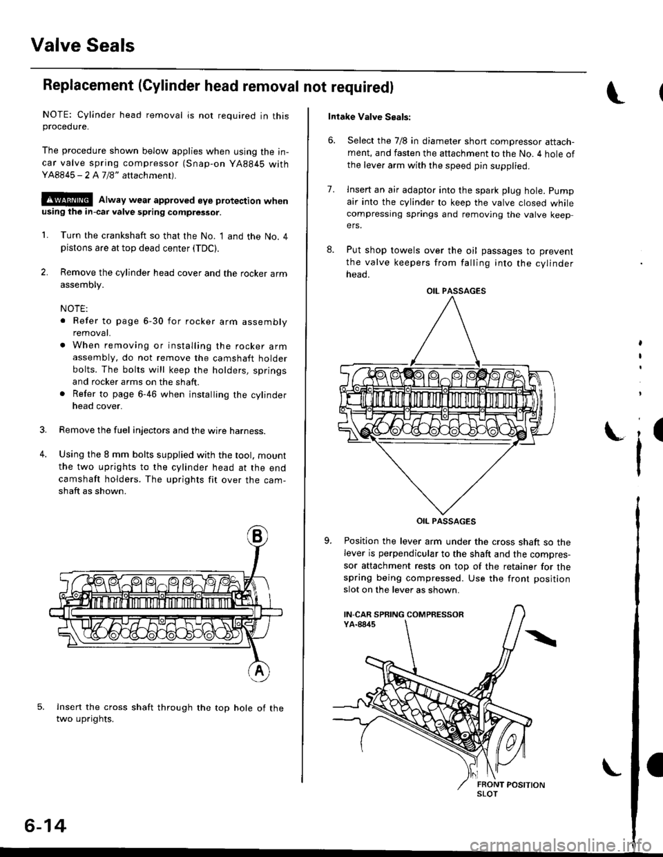
Valve Seals
Replacement (Cylinder head removal not requiredl
NOTE: Cylinder head removal is not required in thisprocedure.
The procedure shown below applies when using the in-
car valve spring compressor (Snap-on YA884S withY48845 - 2 A7/8" attachment).
!@@ Alway wear approved eye protection whenusing ihe in-cai valve spring compressor.
1. Turn the crankshaft so that the No. I and the No. 4pistons are at top dead center (TDC).
2. Remove the cylinder head cover and the rocker arm
assembly.
NOTE:
. Refer to page 6-30 for rocker arm assembly
removat.
. When removing or installing the rocker armassembly, do not remove the camshaft holder
bolts. The bolts will keep the holders, springs
and rocker arms on the shaft.
. Refer to page 6-46 when installing the cylinder
head cover.
Remove the fuel injectors and the wire harness.
Using the 8 mm bolts supplied with the tool. mount
the two uprights to the cylinder head at the end
camshaft holders. The uprights fit over the cam-
shaft as shown.
lnsert the cross shaft through the top hole of thetwo uprights.
3.
4.
6-14
Intake Valve Seals:
6. Select the 7/8 in diameter short compressor attach-ment, and fasten the attachment to the No. 4 hole of
the leve. arm with the speed pin supplied.
8.
7.lnsert an air adapto. into the spark plug hole. pump
air into the cylinder to keep the valve closed whilecompressing springs and removing the valve keepers.
Put shop towels over the oil passages to prevent
the valve keepers from falling into the cylinder
neao.
OIL PASSAGES
Position the lever arm under the cross shaft so thelever is perpendicular to the shaft and the compres-
sor attachment rests on top of the retainer for thespring being compressed. Use the front position
slot on the lever as shown.
,
I
i'
OIL PASSAGES
IN-CAR SPRING COMPRESSOR
SLOT
Page 126 of 2189

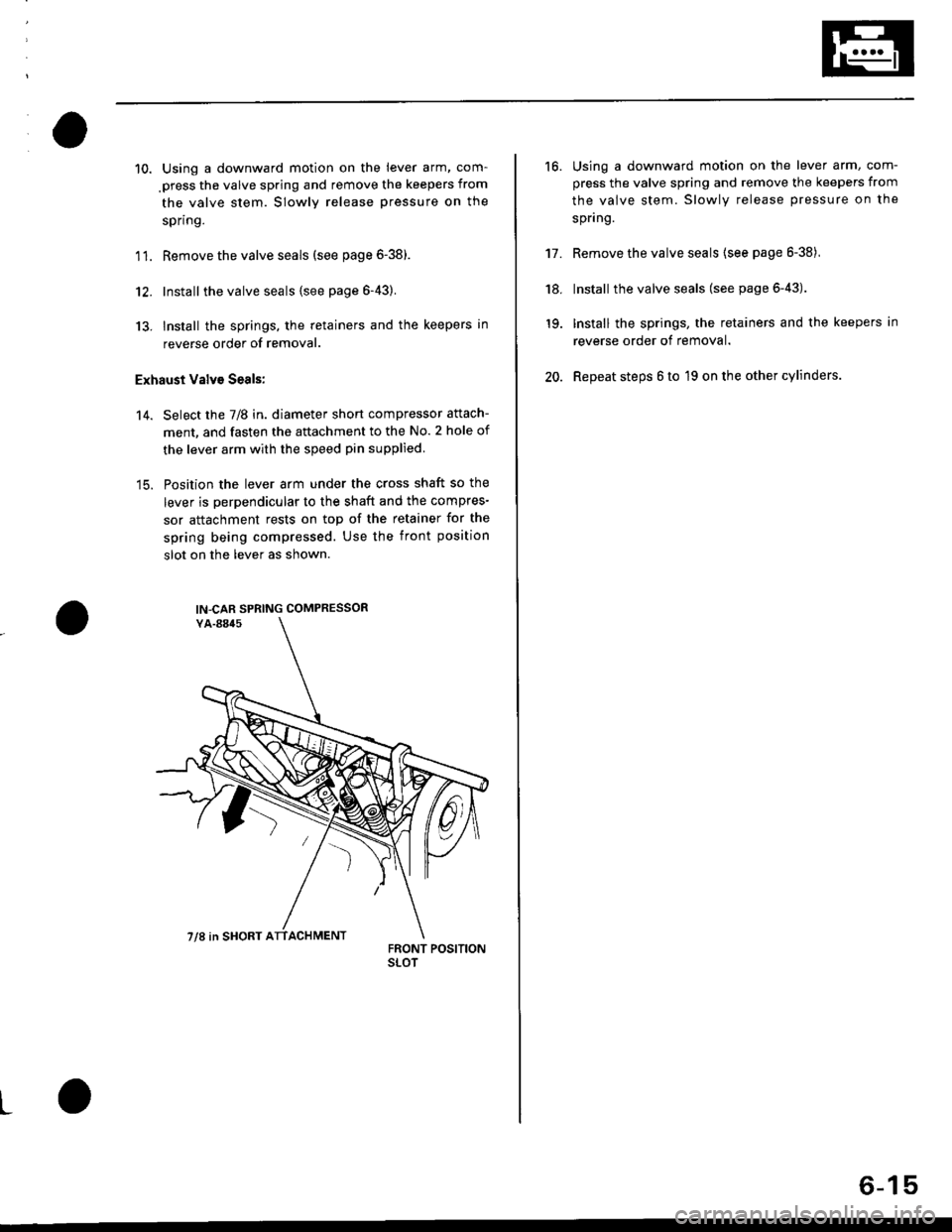
10. Using a downward motion on the lever arm, com-
.press the valve spring and remove the keepers from
the valve stem. Slowly release pressure on the
spring.
11. Remove the valve seals (see page 6-38).
12. Install the valve seals {see page 6-43).
13. Install the springs, the retainers and the keepers in
reverse order of removal.
Exhaust Valvs Sesls:
Select the 7/8 in. diameter short compressor attach-
ment, and fasten the attachment to the No. 2 hole of
the lever arm with the speed pin supplied.
Position the lever arm under the cross shaft so the
lever is perpendicular to the shaft and the compres-
sor attachment rests on top of the retainer for the
spring being compressed. Use the front position
slot on the lever as shown.
'14.
IN-CAR SPRING COMPRESSOR
7/8 in SHORT ATTACHMENT
L
16.Using a downward motion on the lever arm, com-
press the valve spring and remove the keepers from
the valve stem. Slowly release pressure on the
spnng.
Remove the valve seals {see page 6-38),
Install the valve seals (see page 6-43).
Install the springs, the retainers and the keepers in
reverse order of removal.
Repeat steps 6 to 19 on the other cylinders.
't7.
'18.
19.
20.
6-15
Page 281 of 2189
System Description
Vacuum Connections
D16Y5 engin6 ('96 - 97 modelsl:
To EVAPORATIVE EMISSION(EVAPI
TWO WAY VALVE
MANIFOLDABSOLUTEPRESSURE IMAPISENSOR
€VAPORATIVEEMISSION IEVAPIPURGE CONTROL SOLENOIDVALVE
EXHAUST GAS BECIRCULATION(EGR) VALVE end EXHAUST GASRECIRCULATION IEGR) VALVELIFT SENSOR
Qo
FRONT OF VEHICLE
To CRUISECONTROLDIAPHRAGM(wath cruise control)
Qo
O: Vacuum hose No.
11-12
EXHAUST GAS RECIRCULATION(EGR) CONTROL SOLENOID VALVE {CVT}\.'.-' \
I
I
)
FUEL PRESSURE REGULATOR