Page 777 of 2189
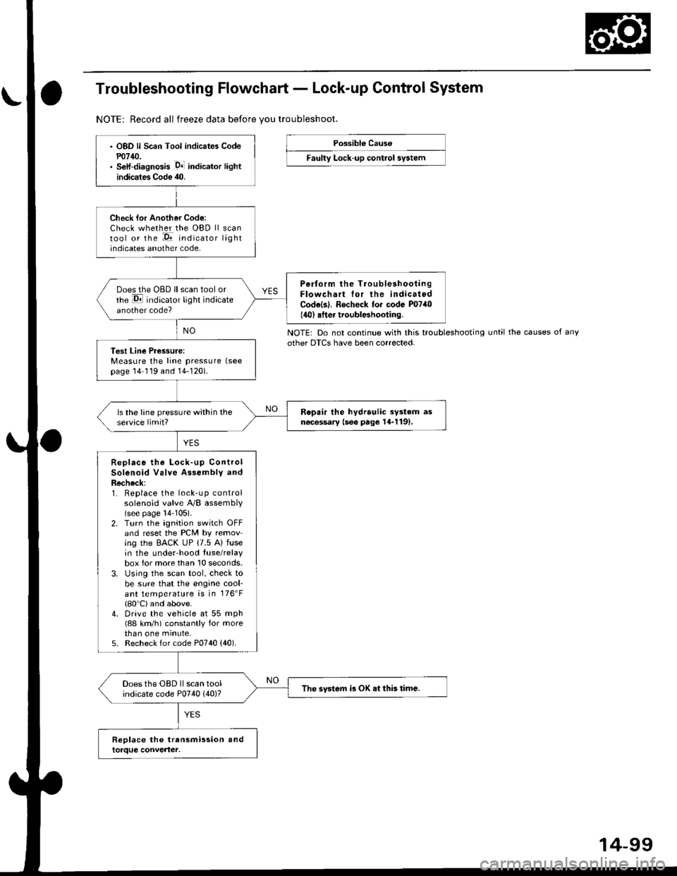
Troubleshooting Flowchart - Lock-up Control System
NOTE: Record all freeze data before vou troubleshoot.
Possibl€ Cause
Faulty Lock-up control sy3tem
NOTE: Do not continue with this troubleshootingother DTCS have been corrected.until the causes of any
OBD ll Scan Tool indicates Codem14/J.S€lf-diagnosis .D4l indicalor lightindicates Code 40.
Check for Another Code:Check whether the OBD ll scantool or the :E indicator lightindicates another code,
Perform the TroubleshootingFlowchart tor the indicatedCodels|. Rocheck to. code P0740(40) .fter troublBhooting.
ooes the OBD ll scan tool orrhe E indicator light indicateanother code?
Test Line Pressure:Measure the line pressure (see
page 14 119 and 14-120).
Repair the hydrrulic sy3tem asn6c6ssary (see page 14-1191.ls the lane pressure within theservice limit?
Replace the Lock-up ControlSolenoid Valve Assembly andRecheck:1. Replace the lock-up controlsolenoid valve A/B assembly(see page 14-105).2. Turn the ignition switch OFFand reset the PCM by removing the EACK UP (7.5 A) fusein the underhood {use/relaybox for more than 10 seconds.3. Using the scan tool, check tobe sure that the engine cool-ant temperature is in 176'F(80'C) and above.4. Drive the vehicle at 55 mph(88 km/h) constantly for morethan one minute,5. Recheck for code P0740 {40).
Does the OBD ll scan toolindicate code P0740 (40)?The svstem i3 OK .t this time.
14-99
Page 778 of 2189
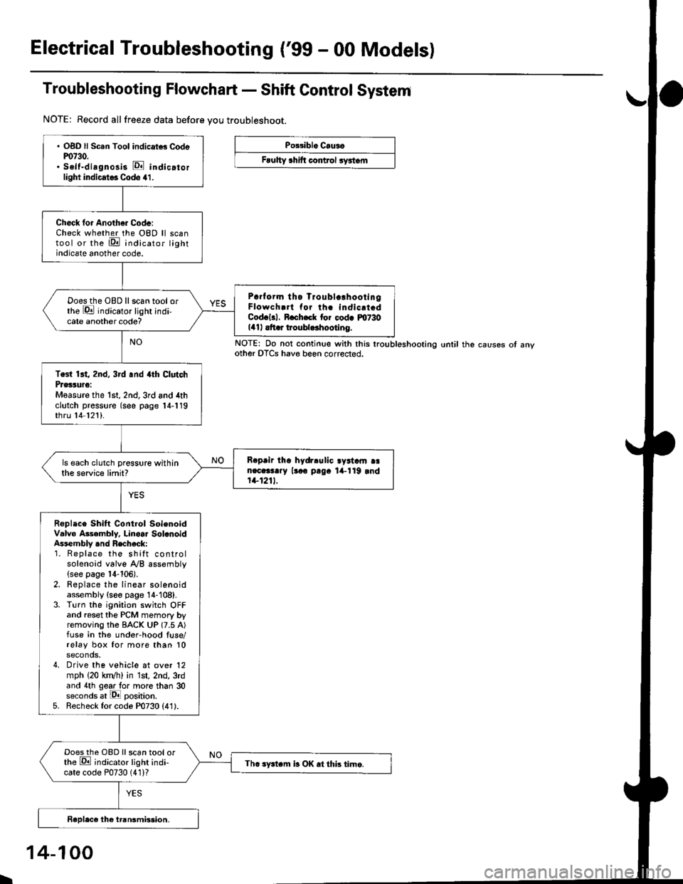
Electrical Troubleshooting ('99 - 00 Modelsl
Troubleshooting Flowchart - Shift Control System
NOTE: Record allfreeze data before you troubleshoot.
Po33ibl. Crus6
Frulty 3hift control ryrtom
. OBD ll Scan Tool indicrtd Codem730.. Self-dirgnosis E indicatorlight indicst€. Codo 41.
Check for Anoth€. Code:Check whether the OBD ll scantool or the E indicator lightindicate another code.
Prrf orm tho Troublc!hootingFlowch.rt for th. indicrt.dCod.l3l. R.ch.ck tor cod. m730141| .tt r troubldhootlng.
Doesthe OBD llscan tool orthe E indicator light indi-cate another code?
Test 13t, 2nd, 3rd .nd 4th ClutchPrglture:Measure the 1st, 2nd,3rd and 4thclutch pressure (see page 14-119thru 14 121).
R.prir tho hydrlulic ayrtam aan.c.3t..y lr.o p!9. lil-119 rnd1+1211.
ls each clutch pressure withinthe service limit?
Roplace Shift Control SolenoidValve Asembly. Linoar Sol.noidAssembly .nd Recheck:1. Replace the shift controlsolenoid valve A/B assembly(see page 14-106).2. Replace the linear solenoidassembly {see page 14-108}.3. Turn the ignition switch OFFand reset the PCM memory byremoving the BACK UP (7.5 A)fuse in the under-hood fuse/relay box for more than 10seconds,4. Drive the vehicle at over 12mph (20 kn/h) in 1st, 2nd, 3rdand 4th gear lo. more than 30seconds at lPll position.5. Recheck for code P0730 (41).
Doesthe OBD Ilscan tool orthe E ;ndicator light indi-cate code P0730 (41)?Th. sFtcm b OK .t this time.
NOTE: Do not continue with this lroubleshooting until the causes ot anyother OTCS have beon corrected.
I
14-100
Page 906 of 2189
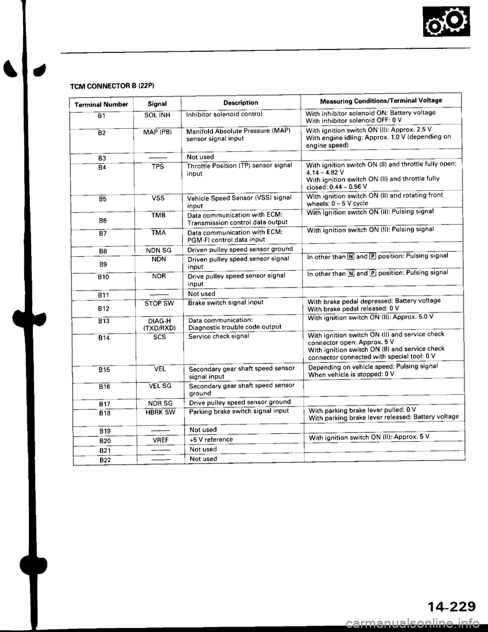
TCM CONNECTOR B (22P}
Terminal NumbelSignalDescriptionMeasuring Conditions/Terminal Voltage
B1SOL INHInhibitor solenoid controlWith inhibitor solenoid ON: Baftery voltage
With inhibitor solenoid OFF: 0 V
82MAP (PB)-M an if old Absol r-rte Pressure IMAP)
sensor signal inPUtWith iqnition switch ON (ll): Approx.2.5 V
With e;gine adling: Approx. 1.0 V (depending on
engine speed)
B3Not used
B4TPS-Throttle Position (TP) sensor signal
input
With ignition switch ON (ll) and throftle fully open:
4.14 - 4.42 VWith ignition switch ON (ll) and throttle fully
closed: 0.44 - 0.56 V
VSSVehicle Speed Sensor (VSS) signal
Inpur
With ignition switch ON (ll) and rotating front
wheelsr 0-5Vcycle
TMBData communication with ECM:
Transmission control data outpUt
With ignilion swltch UN lll): rulslng slgnar
81TMAData communication with EClvl:
PGM Fl control data inPut
With ignition swltch uN {ll,: l-ulslng slgnal
B8NDN SGDriven pulley speed sensor ground
B9NDNDriven pulley speed sensor signal
input
ln other thTnE and E position: Pulsing signal
810NDRDrive pulley speed sensor signal
Input
-tn ottrer ttran E ana E position: Pulsing signal
811Not used
812STOP SWBrake switch signal inPutWith brake pedal depressed: Battery voltage
With brake pedal released: 0 V
813DIAG-H(TXD/RXD)Data communication:Diagnostic trouble code outPut
Wittr ignitio.r s*itct' ON (ll): Approx 5.0 V
814Se-ice ctrect signatWith ignition switch ON (ll) and service check
connector oPen: APProx.5 V
With iqnition switch ON (ll) and service check
"onn"itot. connect"d with special tool: 0 V
Secondary gear shaft speed sensor
signal input
Depending on vehicle speed: Pulsing signal
When vehicle is stoPped: 0 V815VEL
816VEL SGSecondary gear shaft speed sensorgrouno
817NDR SGDrive pulley speed sensor ground
818HBRK SWParking brake switch signal inPutWith parking brake lever pulledr 0 V
With parking brake lever released: Battery voltage
819Not used
B�20VREF+5 V relerenceWith ignition switch ON (ll): Approx 5 V
821Not used
Not used
Page 911 of 2189
Troubleshooting Procedures
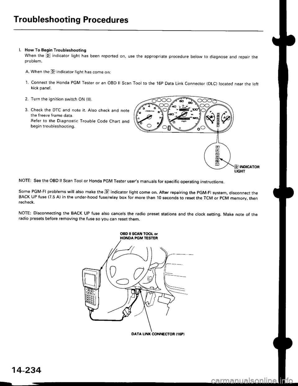
l. How To Begin Troubleshooting
When the E indicator light has been reported on, use the appropriate procedure below to diagnose and repatr theproDlem.
A. When the @ indicator light has come on:
l connect the Honda PGM Tester or an oBD ll Scan Tool to the 16P Data Link Connector (DLc) located near the leftkick panel.
Turn the ignition switch ON (ll).
Check the DTC and note it. Also check and notethe freeze frame data.
Refer to the Diagnostic Trouble Code Chart andbegin troubleshooting.
INOICATORLIGHT
NOTE: SeetheOBDll Scan Tool or Honda PGM Tester user's manuals for specific operating instructions.
Some PGM-FI problems will also make the E indicator light come on. After repairing the pGM-Fl system, disconnect theBACK UP fuse (7.5 Al in the under-hood fuse/relay box for more than l0 seconds to reset the TCM or PCM memory, rnenrecheck.
NOTE: Disconnecting the BACK UP fuse also cancels the radio preset stations and the clock setting. Make note of theradio presets before removing the fuse so you can reset them,
2.
3.
o0\e--loo
OATA LINK CONNECTOB I16P}
14-234
Page 912 of 2189
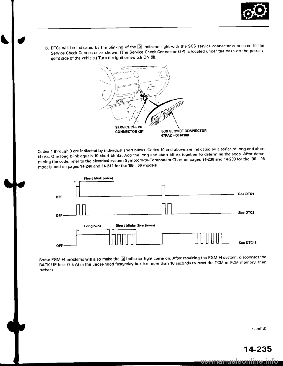
B. DTCS will be indicated by the blinking of the E indicator light with the SCS service connector connected to the
Service Check Connector as shown. (The Service Check Connector (2P) is located under the dash on the passen
ger's side of the vehicle.) Turn the ignition switch ON (ll).
CONNECTOR07PAZ - 00101(x)
codes 1 through 9 are indicated by individual shon btinks. codes 10 and above are indicated by a series of long and short
b|inks.one|ongblinkequa|sloshortb|inks.Addthe|ongandshortb|inkstogethertodeterminethecode.Afterdeter
miningthecode,refertothee|ectrica|systemsymptom-to-componentchartonpagesl4-238and14.239forthe,96_98
models, and on pages 14-240 and 14'241 for the '99 - 00 models
Soc DTCI
Sor DTC2
Long blinkShort blinks |tive tim€sl
some pGM-Ft problems wi
atso make the E indicator light come on. After repairing the PGM-FI system, disconnect the
BACKUPfuse(7.5A)intheUnder.hoodfuse/re|ayboxformorethanl0secondstoresettheTcMorPcMmemory,then
recheck.
Scc DTCI5
(cont'd)
14-235
iii:j
,,,/
CONNECTOR {2PI
Shorl blink (oncc)
Page 913 of 2189
Troubleshooting Procedures
(cont'd)
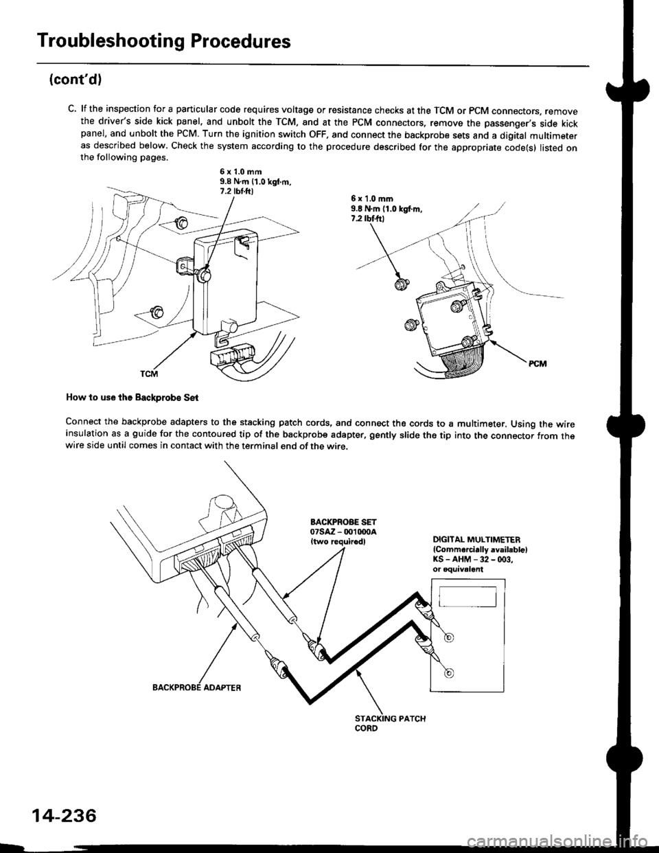
C. lf the inspection for a particular code requires voltage or resistance checks at the TCM or PCM connectors, removethe driver's side kick panel, and unbolt the TCM, and at the PCM connectors, remove the passenger's side kickpanel, and unbolt the PCM. Turn the ignition switch OFF, and connect the backprobe sets and a digital multimeteras described below. Check the system according to the procedure described for the appropriate code(s) listed onthe following pages.
6x1.0mm9.9 N.m {1.0 kgt m,
How to use lhe Backprob€ SE{
Connect the backprobe adapters to the stacking patch cords, and connect the cords to a multimeter, Using the wireinsulation as a guide for the contoured tip of the backprobe adapter, gently slide the tip into the connector from thewire side until comes in contact with the terminal end of the wire.
BACI(PROBE SET07saz - 001 txtoaItwo requirodlDIGITAL MULTIMETER(Commarcially avsibblelKS-AHM-32-(x)3,or oquivalent
6 x 'l,0 mm9.E N.m (1.0 kgf.m,7.2 rbtftt
coRo
14-236
ADAPTER
Page 915 of 2189

Symptom-to-Component Chart
Electrical System -'96 - 98 Models
*: The DTC in parentheses is the code @ indicator light indicates when the Data Link Connector is connected to the HondaPGM Tester.
DTC*O Indicator
LightMILDetection ltemPage
P1790
(3)BlinksONThrottle position sensor14-242
P179'l
(4)BlinksONVehicle speed sensor14-243
P1705
(5)BlinksONAy'T gear position switch (short to groundl't 4-244
P1706
(6)OFFONA/T gear position switch {open)14-246
P0725
(11)BlinksONlgnition coil14-248
P1793
112lBlinksONManifold absolute pressure sensor14-249
P 1870(30)BlinksONShift control linear solenoid14-250
P'1873
(311BlinksONPH-PL control linear solenoid14-25'l
P1879(32)BlinksONStart clutch control linear sotenoid14-252
P1882BlinksONInhibitor solenoid14-253
P1885
(34)BlinksONDrive pulley speed sensor1l-Zb4
P1886(35)BlinksONDriven pulley speed sensor14-255
P1888
(36)BlinksONSecondary gear shaft speed sensor14-256
T to55
(37)BlinksONECM or TCM14-257
P1890
l42lBlinksONShift control system14-259
P1891
(43)BlinksONStart clutch control svstem14-260
14-23a
Page 916 of 2189
lf the self-diagnostic E indicator light does not blink, perform an inspection according to the table below.
SymptomInspectionRef. page
E indicator light does not come on for two seconds after ignition switch
is first turn on (ll).14-262
E indicator light is on constantly (not blinking) whenever the ignition
switch is on (ll).14-264
NOTE:
. lf a customer described the symptom for code P1706 (6), it will be necessary to recreate the symptom by test driving,
then recheck the DTC.
. Sometime the E indicator light and the Malfunction Indicator lamp (MlL) may come on simultaneously. lf so, repair the
pGM-Fl system according to the DTc, then reset the memory by removing the BACK uP fuse in the under-hood
fuse/relay box for more than 10 seconds. Drive the vehicle for several minutes at a speed over 30 mph (50 km/h)' then
recheck the DTC.
14-239