1997 HONDA CIVIC parts
[x] Cancel search: partsPage 1474 of 2189
Troubleshooting
Tips and Precautions (cont'dl
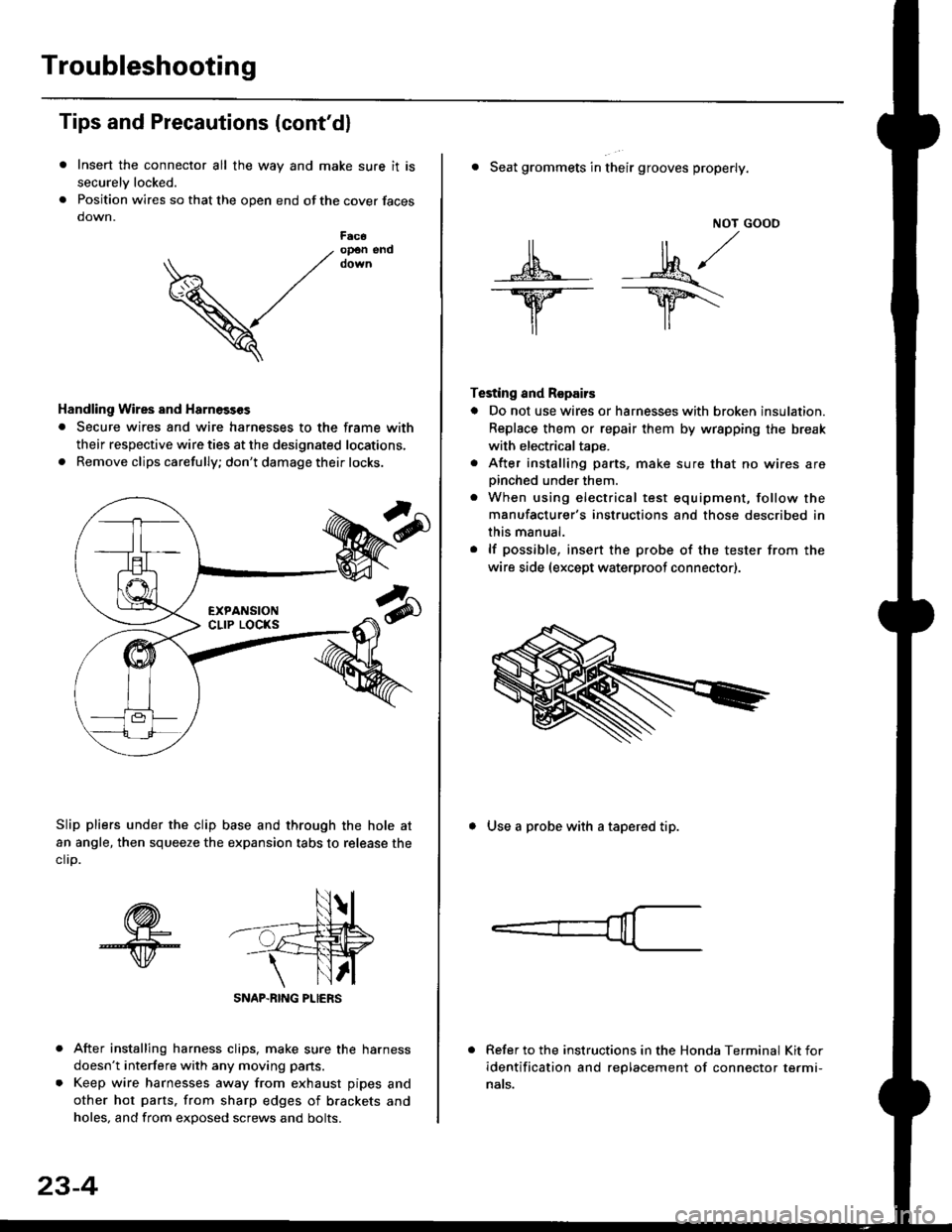
Insert the connector all the way and make sure it is
securelv locked.
Position wires so that the open end of the cover faces
down.
After installing harness clips, make sure the harness
doesn't interfere with any moving pans.
Keep wire harnesses away from exhaust pipes and
other hot parts. from sharp edges of brackets and
holes, and from exDosed screws and bolts.
V
F6c6op€n end
Handling Wires and Harnosscs
. Secure wires and wire harnesses to the frame with
their respective wire ties at the designated locations,
. Remove clips carefully; don't damage their locks.
Slip pliers under the clip base and through the hole at
an angle, then squeeze the expansion tabs to release the
clrp.
SNAP-BING PLIERS
23-4
NOT GOOO
ll il,/
s*' -.1}8."/_Y--_Y5\
il ,,
Testing and Repairs
o Do not use wires or harnesses with broken insulation.
Replace them or repair them by wrspping the break
with electricaltaoe.
. After installing parts, make sure that no wires arepinched under them.. When using electrical test equipment, follow the
manufacturer's instructions and those described in
this manual.
. lf possible, insert the probe of the tester from the
wire side (except waterproof connector).
. Seat grommets in their grooves properly.
. Use a probe with a tapered tip.
Refer to the instructions in the Honda Terminal Kit for
identification and replacement of connector termi-
nats.
Page 1745 of 2189
Precautions/ Procedures
)General Precautions
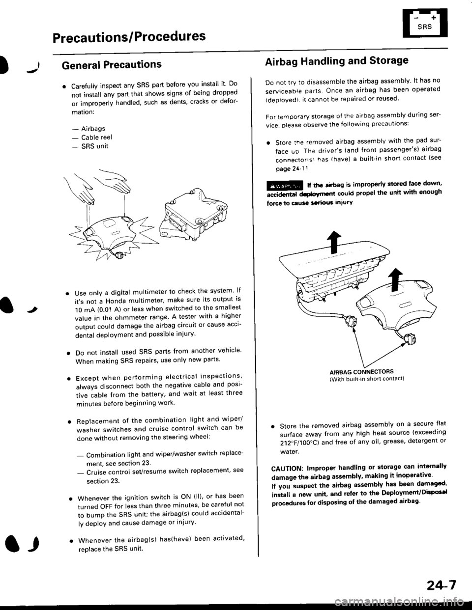
r Carefully inspect any SRS part before you install it Do
not install any part that shows signs of being dropped
or improperly handled' such as dents, cracks or defor-
mation:
- Airbags- Cable reel
- SRS unit
-
Use only a digital multimeter to check the system lf
it's not a Honda multimeter, make sure its output ls
1O mA (0.01 A) or less when switched to the smallest
value in the ohmmeter range. A tester with a higher
output could damage the airbag circuit or cause acci-
dental deployment and possible injury'
I Do not install used SRS parts from another vehicle
When making SRS repairs, use only new pans'
) Except when performing electrical inspections'
always disconnect both the negative cable and posl-
tive cable from the battery, and wait at least three
minutes before beginning work
r Replacement of the combination light and wiper/
washer switches and cruise control switch can be
done without removing the steering wheel:
- Combinalion light and wiper/washer switch replace
ment, see section 23
- Cruise control sevresume switch replacement' see
section 23.
. Whenever the ignition switch is ON {ll), or has been
turned OFF for less than three minutes' be careful not
to bump the SRS unit; the airbag(s) could accidental-
ly deploy and cause damage or injury'
. Whenever the airbag{s) has(have) been activated'
replace the SRS unit.l,
2+7
Airbag Handling and Storage
Do not try to disassemble the airbag assembly. lt has no
serviceable parts Once an airbag has been operated
(deployed). it cannot be repaired or reused'
For temporary storage of the airbag assembly during ser-
vice. olease observe the following precauttons:
. store the .emoved airbag assemblv with the pad sur-
face uo The driver's (and front passenger's) airbag
connecto''s'-as {have) a built.in short contact (see
page 2a-l 1
: | ..r r-+r-a k imninncrlv slorcd lace down,-""dd.r6t dtatltt-,tl could propel the unit whh enough
force lo c.usa 3a.ix! intury
AIRBAG CONNECTORS(With built in shon contact)
. Store the removed airbag assembly on a secure flat
surface away from any high heat source {exceeding
212"FI1OO"CJ and free of any oil' grease, detergent or
water.
CAUTION: lmproper handling or storage can intern'lJy
damage the airbag assembly, making it inoperativo
lf you suspect the airbag assembly has been dam€cd'
inslall a new unit. and relsr lo the Deployment/DisPG'l
olocedules for disposing ol the damaged airbag
Page 1747 of 2189
)
Wiring Precautions
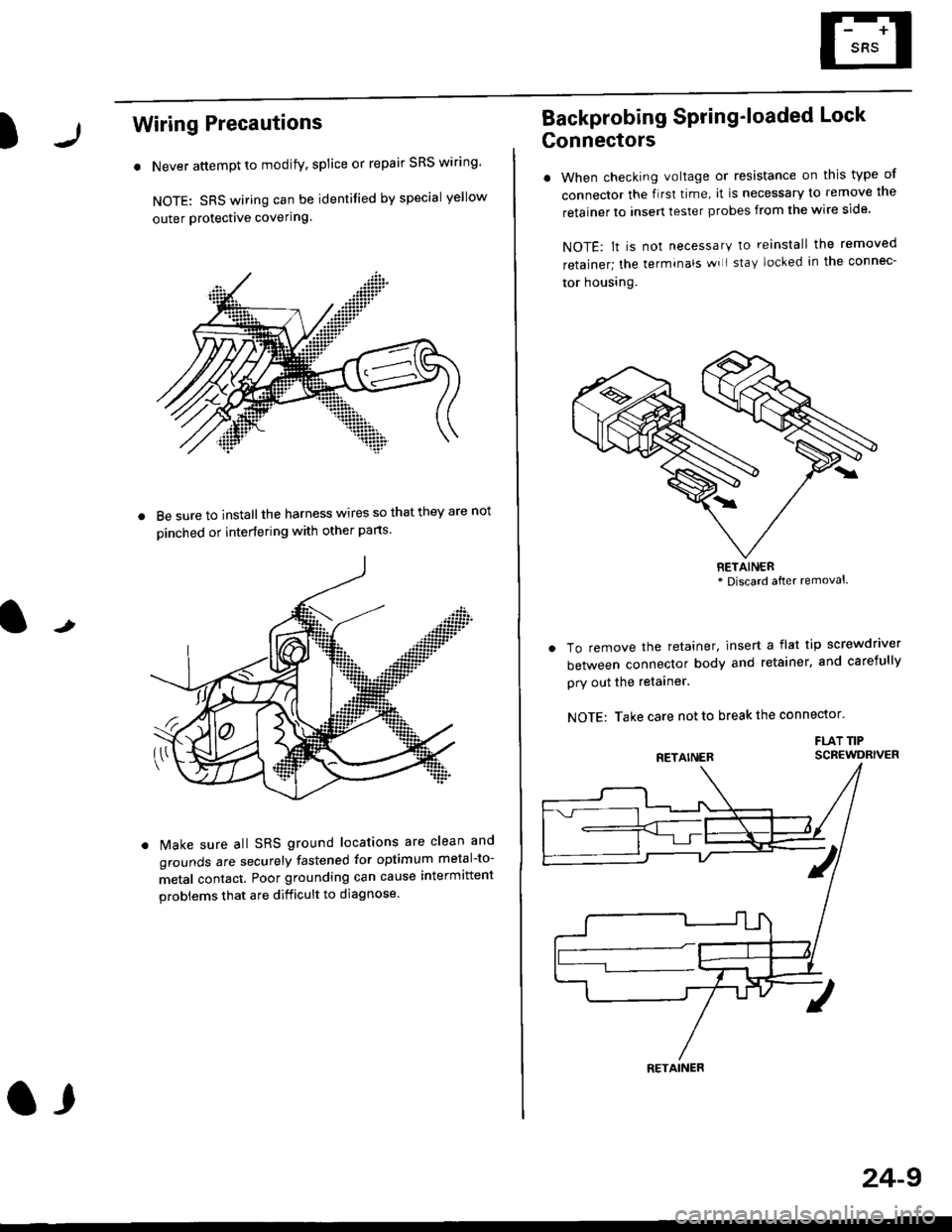
. Never attempt to modify, splice or repair SRS wiring'
NOTE: SRS wiring can be identified by special yellow
outer Protective covering.
8e sure to install the harness wires so that they are not
oinched or interfering with other parts.
t
Make sure all SRS ground locations are clean and
grounds are securely fastened for optimum metal-to-
metal contact. Poor grounding can cause intermittent
problems that are difficult to diagnose.
a,
24-9
Backprobing Spring'loaded Lock
Gonnectors
. When checking voltage or resistance on this type of
connector the flrst time, it is necessary to remove lne
retainer to insert tester probes from the wire side.
NOTE: lt is not necessary to reinstall the removed
retainer; the terminals wi I stay locked in the connec-
tor housrng.
To remove the retainer, insert a flat tip screwdriver
between connector body and retainer, and carefully
pry out the retainer.
NOTE: Take care not to break the connector.
FLAT TIPSCBEWDRIVER
RETAINER* Discard after removal.
RETAINER
Page 1750 of 2189
Precautions/Procedu res
Steering-related Precautions
Stesring Wheel and Cable Reol Alignment
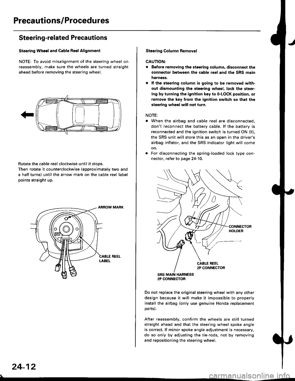
NOTE: To avoid misalignment of the steering wheel on
reassembly, make sure the wheels are turned straight
ahead before removing the steering wheel.
Rotate the cable reel clockwise until it stops.
Then rotate it counterclockwise {approximately two and
a half turns) until the arrow mark on the cable reel label
points straight up.
24-12
:l
St€€rin9 Column Removal
CAUTION:
. Eefore removing thg stggring column. disconnect the
connsstor bqtween the cable r€el and th€ SRS msin
harness.
. lf the stoering column is going to be romoved with-
out dismounting th6 stoering wheel, lock the steer-
ing by turning the ignition key to o-LOCK position, or
remove the key trom the ignition switch so that the
steering wheel will not turn.
NOTE:
When the airbag and cable reel are disconnected,
don't reconnect the battery cable. lf the battery is
reconnected and the ignition switch is turned ON (ll),
the SRS unit will store this as an open in the driver's
airbag inflator, and the SRS indicator light will come
on.
For disconnecting the spring-loaded lock type con-
nector, refer to page 24-'10.
SRS MAIN HARNESS2P CONNECTOR
Do not replace the original steering wheel with any other
design because it will make it impossible to properly
install the airbag (only use genuine Honda replacement
parts).
After reassembly, confirm the wheels are still turned
straight ahead and that the steering wheel spoke angle
is correct. lf minor spoke angle adjustment is necessary,
do so only by adjusting the tie-rods, not by removing
and repositioning the steering wheel.
Page 1754 of 2189
Troubleshooting
SRS Unit ldentification
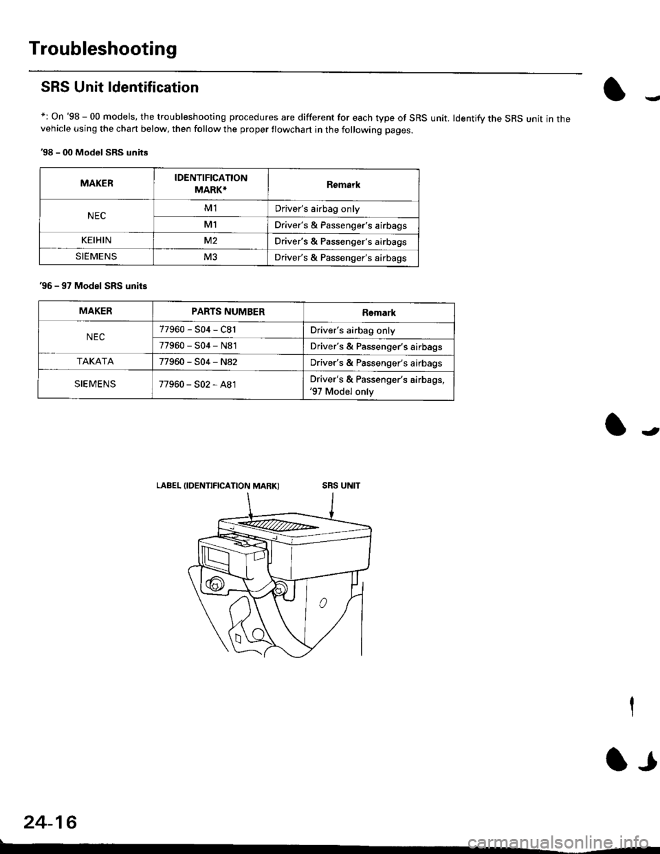
+: On '98 - 00 models, the troubleshooting procedures are different for each type of SRS unit. ldentifv the SRS unit in thevehicle using the chart below, then follow the proper flowchan in the following pages.
'98 - 00 Model SRS units
MAKERIDENTIFICATION
MARK*Remark
NECM1Driver's airbag only
M1Driver's & Passenger's airbags
KEIHINM2Driver's & Passenger's airbags
SIEMENSM3Driver's & Passenger's airbags
'96 - 97 Model SRS units
LABEL IIDENTIFICATION MARK)
MAKERPARTS NUMBERRemark
NEC77960-S04-C81Driver's airbag only
77960-S04-N81Driver's & Passenger's airbags
TAKATA77960-S04-N82Driver's & Passenger's airbags
SIEMENS77960-S02-A81Driver's & Passenger's airbags,'97 Model only
24-16
lr
Page 1805 of 2189
Airbag
)Replacement
After a collision in which the airbags were deployed' the
airbag assemblies and the SRS unit must be replaced'
!!!@ Store a removed airbag with the pad sur'
iFup. rr trt" airbag is improperly stored face down'
accidental deployment could propel the unit with
enough force to cause serious iniury'
CAUTION:
. Always disconnsct lhe airbag conn€ctor(s) when the
harness is disconnected.
. Do not disassemble or tamper with the ailbag'
NOTE:
. Do not install used SRS parts from another vehicle'
When repairing, use only new SRS parts'
o Carefully inspect the airbag before you install it Do
not insiall an airbag that shows signs oI being
dropped or improperly handled, such as dents' cracks
or deformation.
1. Disconnect the battery negative cable' then discon-
nect the positive cable from the battery' and wait at
least three minutes
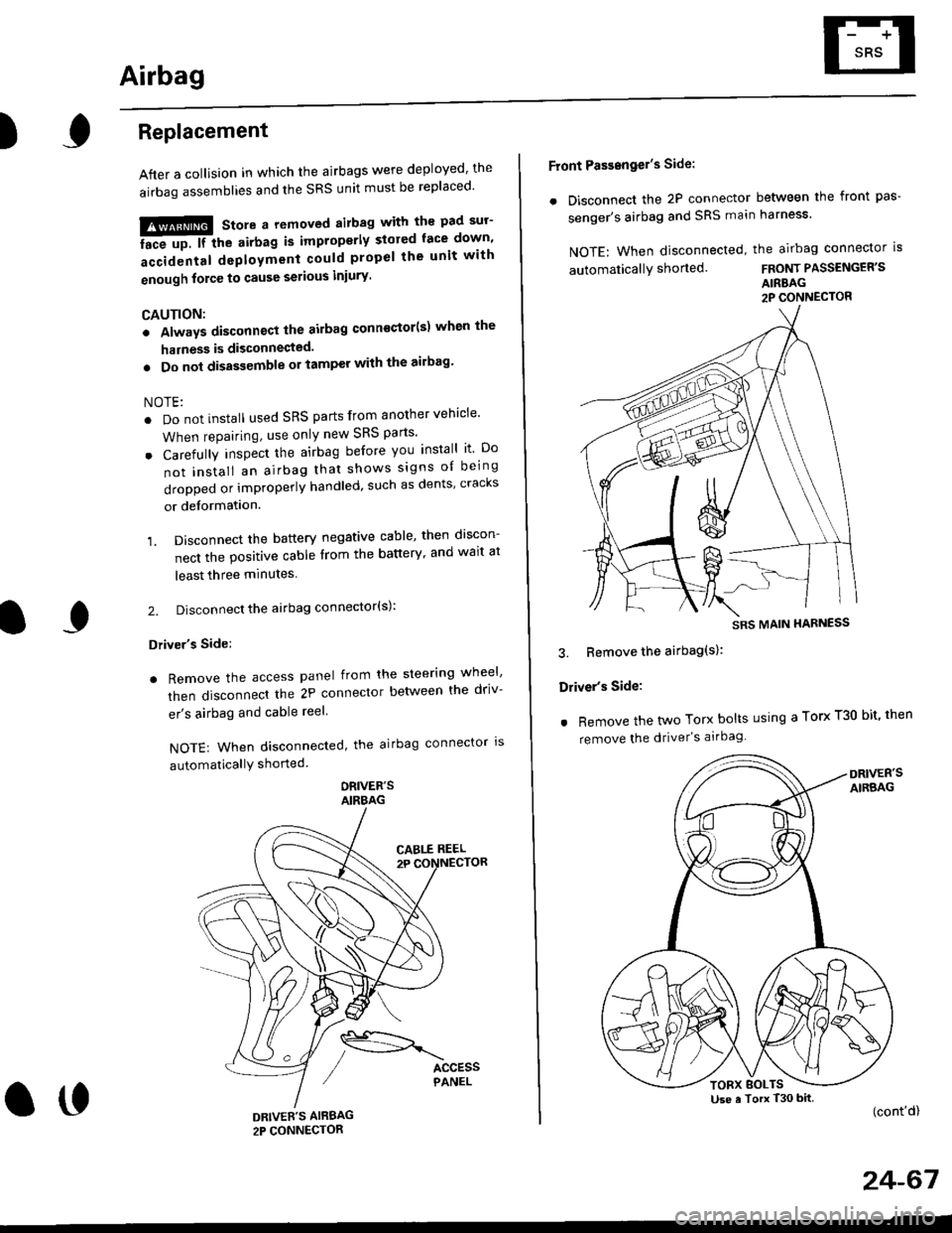
2. Disconnect the airbag connector(s):
Driver's Side:
. Remove the access panel from the steering wheel'
then disconnecl the 2P connector betlveen the driv-
er's airbag and cable reel
NOTE: When disconnected, the airbag connector ls
automaticallY shorted
ORIVER'SAIRBAG
DRIVEE'S AIRBAG2P CONNECTOR
oo
Front Passengel's Side:
. Disconnect the 2P connector between the front pas-
senger's airbag and SRS main harness'
NOTE: When disconnected, the airbag connector is
automaticallY shorted.FRONT PASSENGER'S
AIRBAG2P CONNECTOR
3. Bemove the airbag(s):
Driver's Side:
. Remove the two Torx bolts using a Torx T30 bit' then
remove the driver's airbag
(cont'd)
24-67
SRS MAIN HARNESS
Use a Torx T30 bitTORX BOLTS
Page 1806 of 2189
Airbag
Replacement (cont'd)
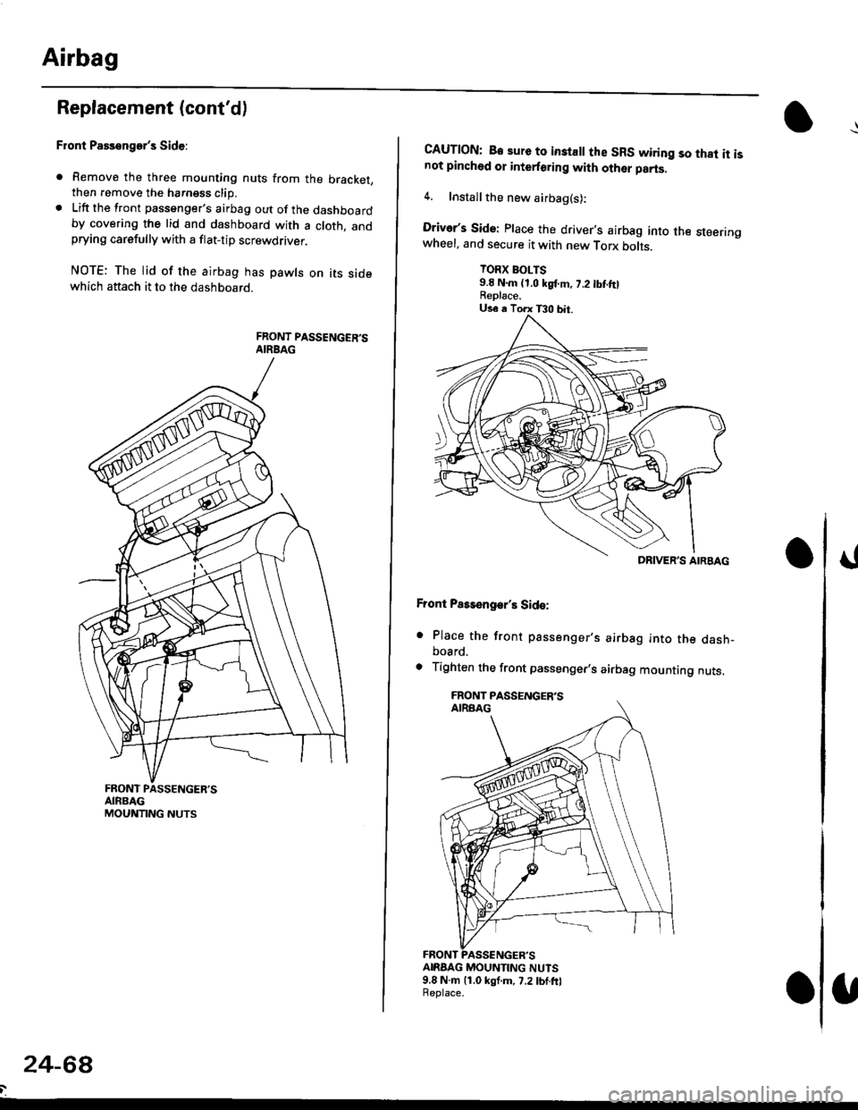
Front Passenger's Side:
. Remove the three mounting nuts from the bracket,then remove the harngss clip.. Lift the front passenger's airbag out of the dashboardby covering the lid and dashboard with a cloth, andprying carefully with a flat-tip screwdflver.
NOTE: The lid of the airbag has pawls on its sidewhich attach it to the dashboard.
24-6a
CAUTION: B€ sure to inslall the SRS wiring so that it isnot pinched or interforirg with other parts.
4. Installthe new airbag(s):
Driver's Side: Place the driver,s airbag into the steeringwheel, and secure it with new Torx botrs.
TORX BOLTS9.E N.m (1,0 kgf.m, 7.2 tbt ftlReplace.
Front Pass€ngar's Side:
. Place the front passenger,s airbag into the dash-board.
. Tighten the front passenger,s airbag mounting nuts.
ANAAG MOUNTING NUTS9.8 N.m 11.0 kgf.m, 7.2lbf.frlReplace.
DRIVER'S AIRBAG
Page 1808 of 2189
Airbag
Disposal
Before scrapping any airbags (including those in a wholevehicle to be scrapped), the airbags must be deployed. lfthe vehicle is still within the warranty period, before youdeploy the airbags, the Honda District Service Managermust give approval and/or special instructions. Onlv afterthe airbags have been deployed (as the result of vehiclecollision, for example), can they be scrapped.lf the airbags appear intact (not deployed). treat themwith extreme caution.
Follow this p.ocedure:
Deploying the Airbags: In.vehiclo
NOTE: lf an SRS vehicle is to be entirely scrapped, itsairbags should be deployed while still in the vehicle. Theairbags should not be considered as salvageable partsand should never be installed in another veh;cle.
!@ confirm thst oach airbag assembty issecurely mounted; otharwiso. sev€re personal iniurycould result lrom deployment.
1. Disconnect the baftery negative cable, then discon_nect the positive cable.
2. Confirm that the special tool is functioning properlyby following the check procedure on the tool labelor on page 24-'l'l .
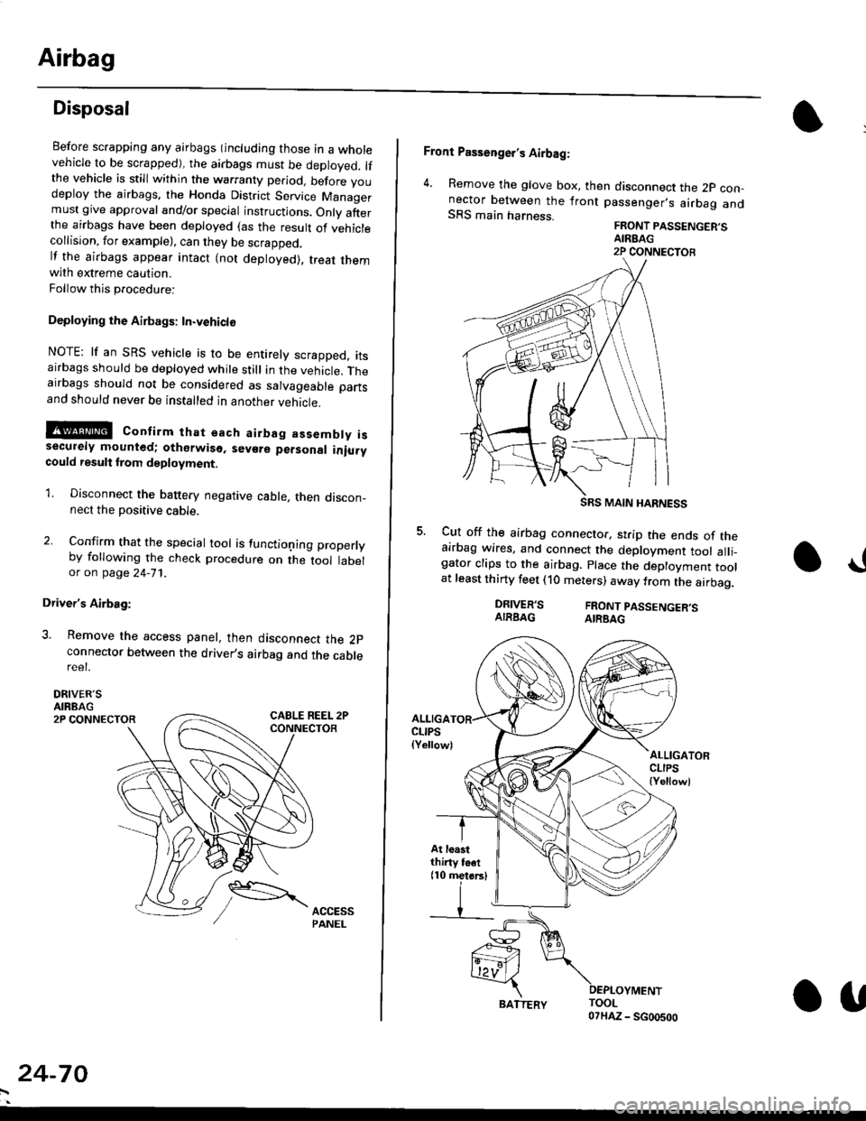
Driver's Airbag:
3. Remove the access panel, then disconnect the 2pconnector between the driver,s airbag and the cablereet.
DRIVER'SAIRBAG2P CONNECTOR
24-70
BATTERY.U
Front Passenger's Airbag:
4. Remove the glove box, then disconnect the 2p con-nector between the lront passenger,s airbag andSRS main harness.FRONT PASSENGER'SAIREAG2P CONNECTOB
SRS MAIN HARNESS
Cut off the airbag connector, strip the ends of theairbag wires, and connect the deployment tool alli_gator clips to the airbag. place the deployment toolat least thirty feet (10 meters) away from the airbag.
a!
DRIVER'SAIRBAGFRONT PASSENGER'SAIRBAG
ALLIGACLIPS(Yellow)ALLIGATORCLIPS{Yellowl
At loastthiny toet(10 metorsl