Page 1298 of 2189
Dashboard
Component RemovaUlnstallation
CAUTION: When prying with a flat-tip screwdriver,
wrap it with protoctivo tape, and apply protective tape
around tho r6lat6d parts, to prevent damag6.
NOTE: Take care not to scratch the dashboard and relatedpans.
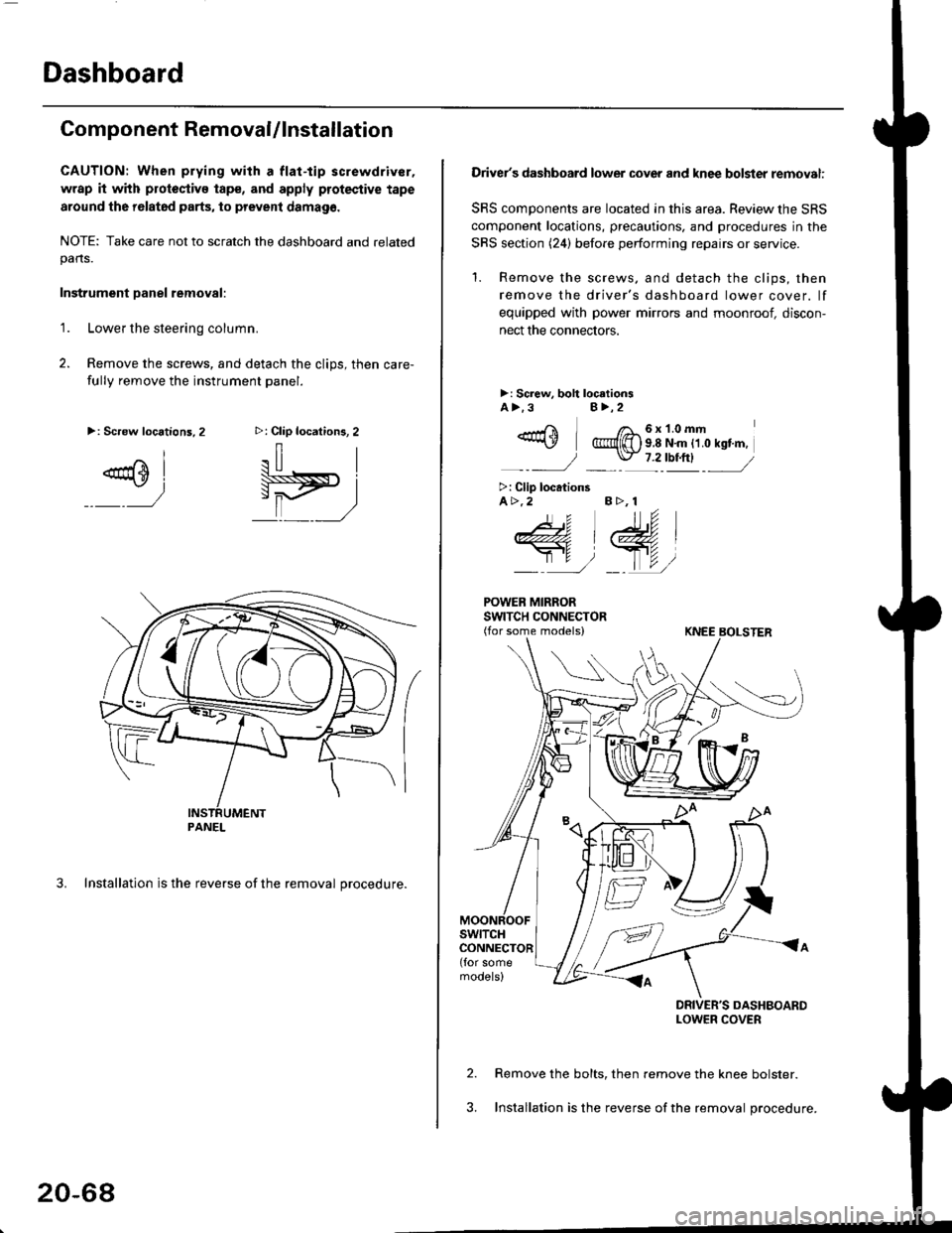
Instrument Danel removal:
1.Lower the steering column.
Remove the screws, and detach the clips, then care-
fully remove the instrument panel.
3. Installation is the reverse of the removal procedure.
>: Clip locations, 2
.il |
Pit)_ _ ,/
>: Screw locations,2
^l
@sl
:)
PANEL
20-68
Driver's dashboard lower cover and knee bolster removal:
SRS components are located in this area. Review the SRS
component locations, precautions. and procedures in the
SRS section (24) before performing repairs or service.
'1. Remove the screws, and detach the clips, then
remove the driver's dashboard lower cover. lf
equipped with power mirrors and moonroof, discon-
nect the connectors.
>: Screw, boh loc.tionsA>.3B>,2
_-rri I /a_6x1.0mm*\Y @{[) s 8 N'm tt o rst'm,
_-_- J _ \J- 7 2_rbtftl -_
>: Clip locationsA>.2 B >, 1
tu
DRIVER'S DASHBOARDLOWER COVER
Remove the bolts, then remove the knee bolster.
Installation is the reverse of the removal procedure.
Page 1300 of 2189
Dashboard
Gomponent Removal/lnstallation
(cont'd)
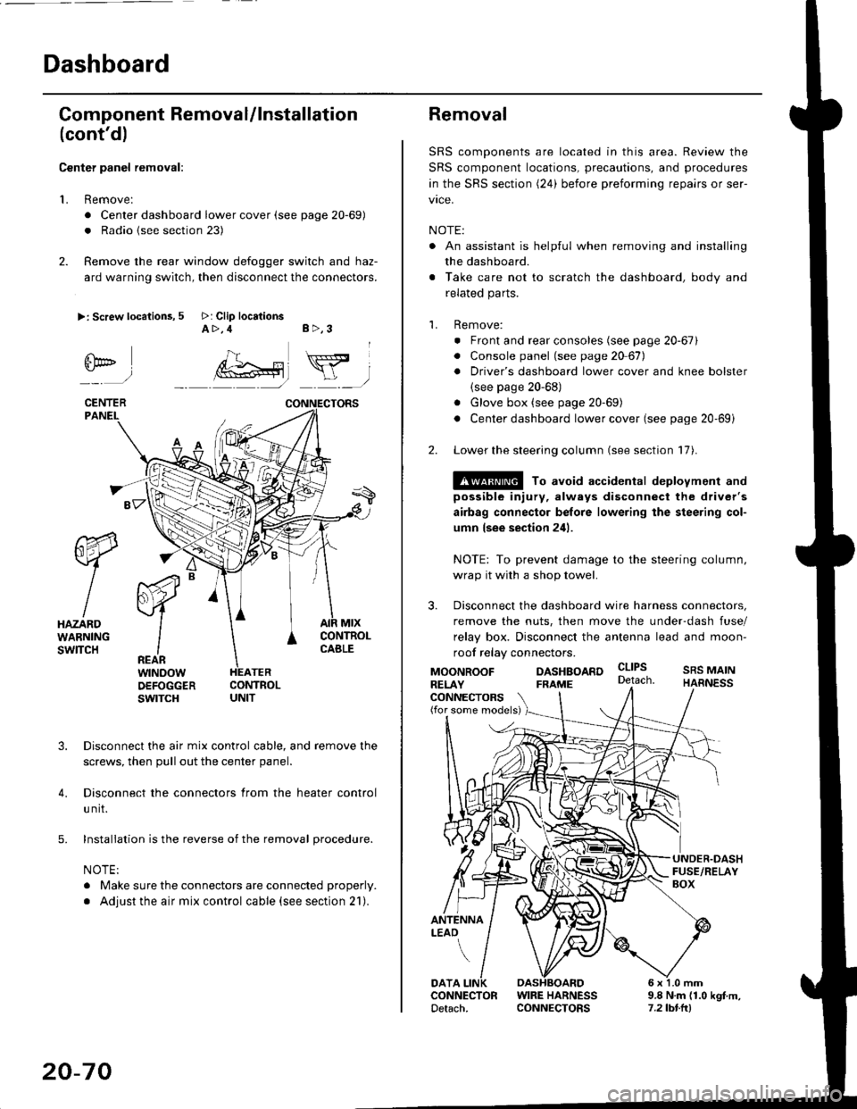
Center panel removal:
1. Remove:
. Center dashboard lower cover (see page 20-69)
. Radio {see section 23)
2. Remove the rear window defogger switch and haz-
ard warning switch, then disconnect the connectors.
>: Screw locations, 5 >: Clip locationsA>,4 B>,3
fii*-)
CENTERPANEI.
rt-xR.
W
IHAZARDWARNINGswlTcH
r44 "
F.IZvl
IIREARwtNoowOEFOGGERswtrcH
MtxCONTNOLCABLE
3. Disconnect the air mix control cable, and remove the
screws, then pull out the center panel.
4. Disconnect the connectors from the heater control
u nit.
5. Installation is the reverse of the removal procedure.
NOTE:
. Make sure the connectors are connected properly.
. Adjust the air mix control cable (see section 21).
20-70
Removal
SRS components are located in this area. Review the
SRS component locations, precautions, and procedures
in the SRS section (24) before preforming repairs or ser-
vice.
NOTE:
. An assistant is helpful when removing and installing
the dashboard.
. Take care not to scratch the dashboard, body and
related parts.
1. Remove:
o Front and rear consoles (see page 20-67)
. Console panel (see page 2O 67),
. Driver's dashboard lower cover and knee bolster(see page 20-68)
. Glove box (see page 20-69)
. Center dashboard lower cover (see page 20-69i
2. Lower the steering column (see section 17).
@ To avoid accidental deplovment and
possible injury, always disconnect the driver's
airbag connector belore lowering the steering col-
umn lsee section 241.
NOTE: To prevent damage to the steering column,
wrap it with a shop towel.
3. Disconnect the dashboard wire harness connectors,
remove the nuts, then move the under-dash fuse/
relay box. Disconnect the antenna lead and moon-
roof relay connectors.
DASHBOARD cltPs
CONNECTORS(for some models)
MOONROOFRELAY
ANTENNALEAO
FRAME
SRS MAINHARNESS
9.8 N.m (1.0 kgf m,7.2lbt.ltl
DATACONNECTOR WIRE HARNESSDetach. CONNECTORS
Page 1301 of 2189
Remove the following parts Irom the dashboard'
. Driver's dashboard side cover
o Passenger's dashboard lower cover
. Dashboard center lid
Disconnect the connectors and air mix control cable'
6x1.0mm9.8 N.m 11.0 kgl.m,
D>, 1
@7 2'orftl - ---//_._J
,{nil Lll , ,"o
Ift#5 L //Hl Wlj%u|5 i//Wt qT
W72-t11 7'::--J
>: Clip locationsA>, 1 B>, 1
Loosen the bolt.
DASHBOARD
AIR MIX CONTROL
CONNECTORS
FRONT PASSENGER'SAIRBAG CONNECTOR
Remove the bolts, then lift and remove the dashboard'
CAUTION: Use proteqtive plates on the bottom ot the front pillar trim'(cont'd)
20-71
M,::;:"lx3T:iJnif:3lilH:fl"*:1::f"*'il;ili"'"
disconnect rhe front passeneer's airbas
>: Bolt, screw locaiions
A>,7B>, 1
,i( 8x125mm(!,@ 22 N.m t2.2 kstm,-v, 16 tbf.ftl
8xl.25mm I22 N.m 12.2 kgt'm, I'"tt:___J
c>, 1
@
c>,6
Page 1321 of 2189
Seat Belts
Inspection
t.
Retractor InsDection
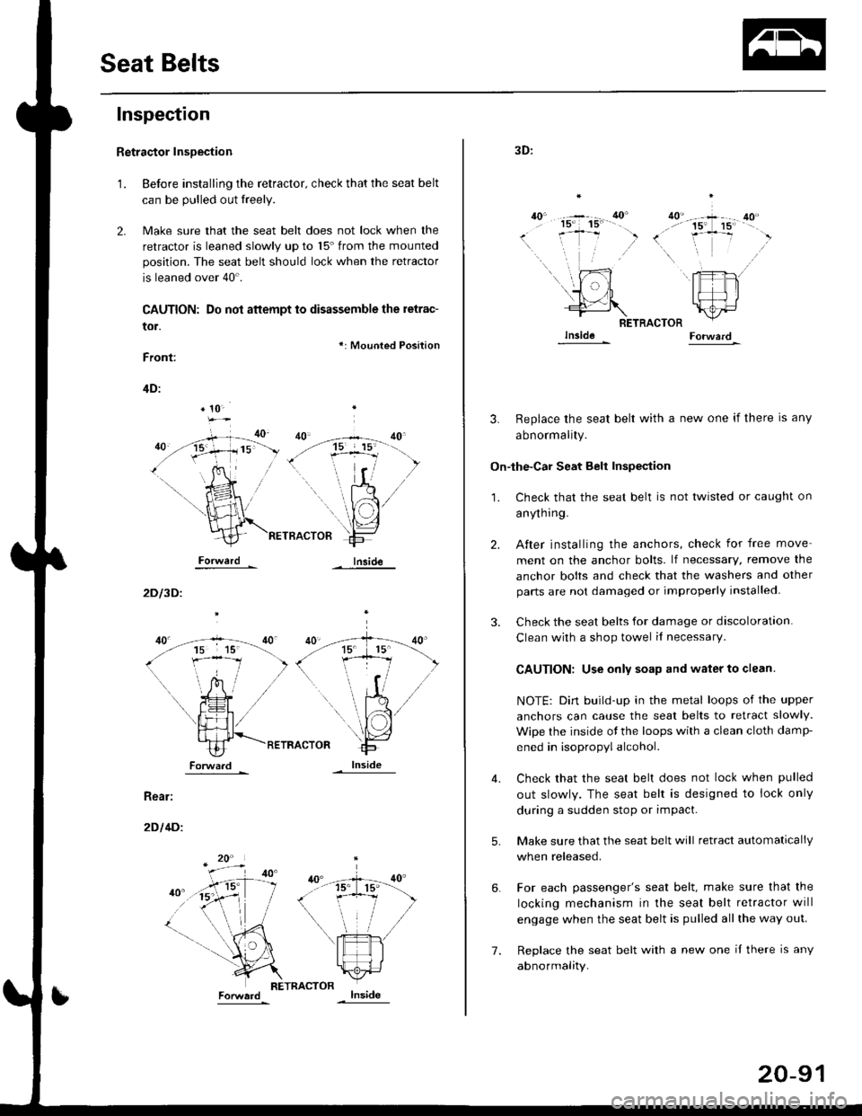
Before installing the retractor, check that the seat belt
can be pulled out freely.
Make sure that the seat belt does not lock when the
retractor is leaned slowly up to 15'from the mounted
position. The seat belt should lock when the retractor
is leaned over 40'.
CAUTION: Do not attempt to disassemble the retrac-
tor.
Front:
*: Mounted Position
Inside
4D:
Forward
2D l3D.
Rear:
2D l4Di
* 10-
15 15'
i-Tl
I ],f
ForwaJdlnside
7.
20-91
3D:
ao"40'- -+ 40...'' 15' 15' --
(. .-j- ,)\,
RETRACTOR
3. Replace the seat belt with a new one if there is any
abnormality.
On-lhe-Car Seat Belt Inspeqtion
2.
3.
1.
5.
6.
4.
Check that the seat belt is not twisted or caught on
anyrn I ng.
After installing the anchors, check for free move
ment on the anchor bolts. lf necessary, remove the
anchor bolts and check that the washers and other
parts are not damaged or improperly installed
Check the seat belts for damage or discoloration.
Clean with a shop towel il necessary
CAUTION: Use only soap and water to clean.
NOTE: Dirt build-up in the metal loops of the upper
anchors can cause the seat belts to retract slowly.
Wipe the inside ot the loops with a clean cloth damF
ened in isopropyl alcohol.
Check that the seat belt does not lock when pulled
out slowly. The seat belt is designed to lock only
during a sudden stop or impact.
Make sure that the seat belt will retract automatically
when released.
For each passenger's seat belt, make sure that the
locking mechanism in the seat belt retractor will
engage when the seat belt is pulled all the way out.
Replace the seat belt with a new one il there is any
abnormality.
Page 1338 of 2189
Opener Cables
Replacement
NOTE:
t When removing the clips. use a clip remover.. Take care not to bend the opener cables.
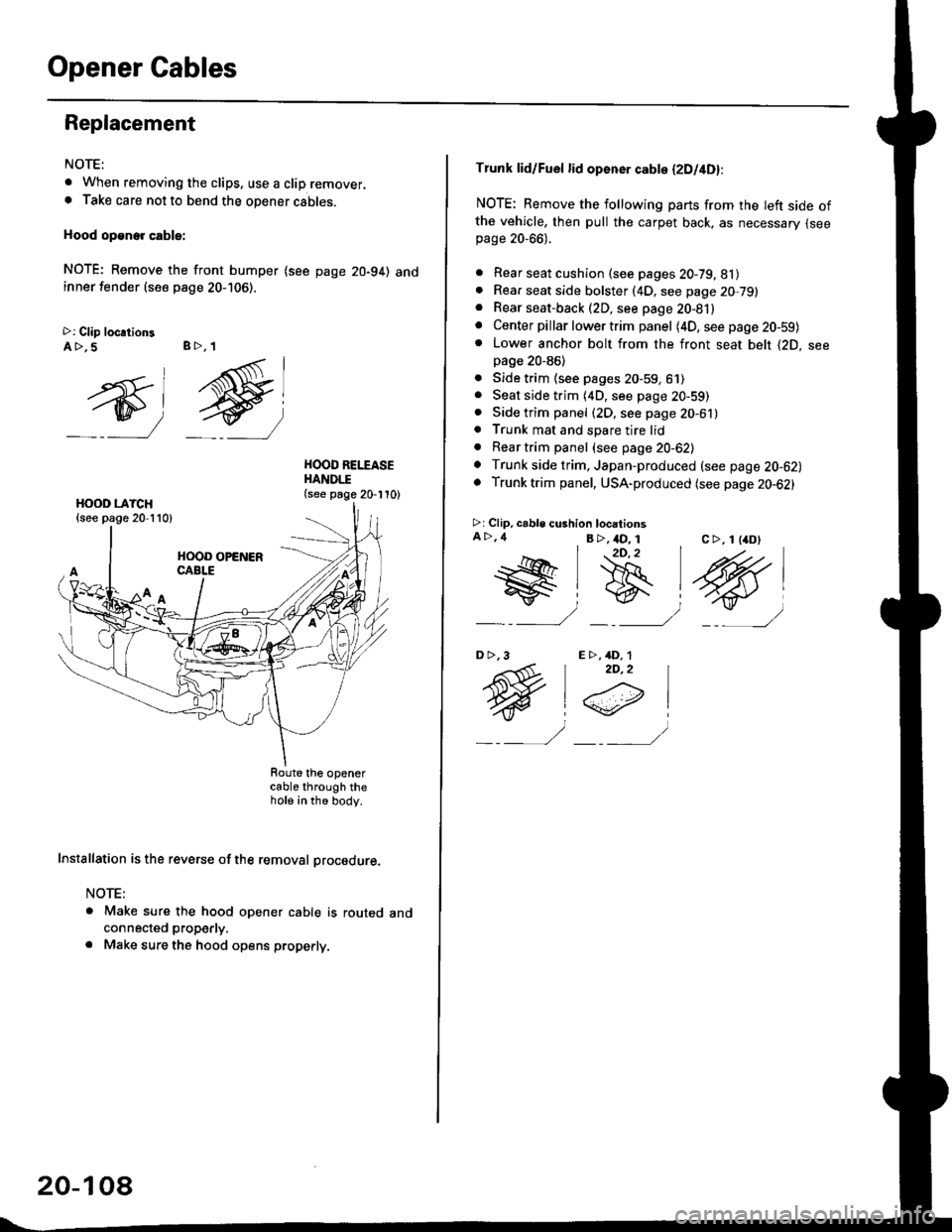
Hood op€ne. cable:
NOTE; Remove the front bumper (see page 20-94) andinner fender (see page 20-106).
>: Clip loc.tionsA >,5 B>, 1
ry)
g
HOOD REI.TASEHANDI.I(see page 20-110)
cable through thehote in th6 body.
Installation is the reverse of the removal procedure.
NOTE:
a Make sure the hood opener cable is routed andconnected properly.
. Make sure the hood opens properly.
20-10a
Tlunk lid/Fuel lid opener cabte (2Dl4D):
NOTE: Remove the following parts from rhe Ieft side ofthe vehicle, then pull the carpet back, as necessary {seepage 20-66).
. Rear seat cushion (see pages 20-79, 81). Rear seat side bolster (4D, see page 20,79). Rear seat-back (2D, see page 20-81). Center pillar lower trim panel (4D, seepage20-59)o Lower anchor bolt from the front seat belt {2D. seepage 20-86)
. Side trim (see pages 20-59, 61). Seat side trim (4D, see page 20-59). Side trim panel (2D, see page 20-61). Trunk mat and spare tire lid. Reartrim panel (see page 20-62). Trunk side trim, Japan-produced (see page 20-62). Trunk trim panel, USA-produced (see page 20-62)
>r Clip, cable cushion locationsA >,4 B >,4D_ 1c >, 1 l4D)2D,2
t@#lB
_ : _/ _-___)
E >,4D, 12D,2
@i
_ _,, -/
D>,3
Page 1340 of 2189
Opener CablesOpener and Latch
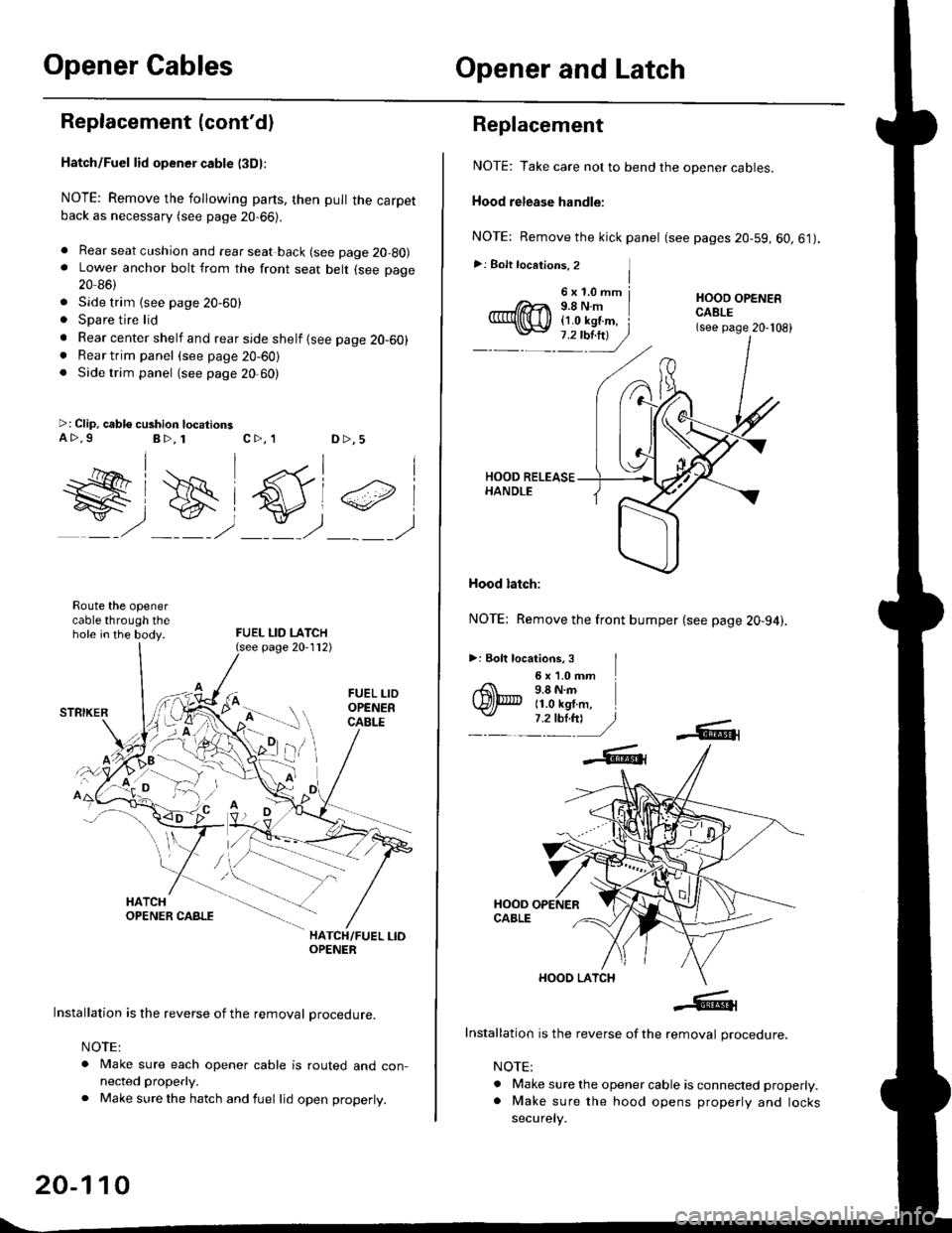
Replacement (cont'dl
Hatch/Fuel lid opener cable l3Dl:
NOTE: Remove the following parts, then pull the carpetback as necessary (see page 20-66).
. Rear seat cushion and rear seat back (see page 20-80). Lower anchor bolt from the front seat belt (see page
20 86)
. Side trim {see page 20-60). Spare tire lid
. Rear center shelf and rear side shelf {see page 20-60). Rear trim panel (see page 20-60). Side trim panel (see page 20,60)
>: Clip, cable cushion locationsa>.9B>, 1c>, 1D >,5
W#)
FUEL LID LATCH
#,
Route the openercable through thehole in the body.
HATCH/FUEL LIOOPENER
Installation is the reverse of the removal procedure.
NOTE:
. Make sure each opener cable is routed and con-nected properly.
. Make sure the hatch and fuel lid open properly.
page 20-112)
20-110
6x1.0mm j9.8Nm{1.0 kgf.m, i
Replacement
NOTE: Take care not to bend the opener cables.
Hood release handle:
NOTE: Remove the kick panel (see pages 20-59, 60.61).
>: Bolt locations, 2 ]I
HOOO OPENERCABLE(see page 20-108)
Hood latch:
NOTE: Remove the front bumper (see page 20-94).
>: Eolt locations, 3 I6 x '1.0 mm9.8 N.m11.0 kgf.m,
Installation is the reverse of the removal procedure.
NOTE:
. Make sure the opener cable is connected properly.. Make sure the hood opens properly and locks
securely.
Page 1344 of 2189
Windshield Wiper Arms and Linkage
Replacement (cont'dl
USA-produced:
3. Separate the windshield wiper linkage and wind-
shield wiper motor.
Japan/Canada-produced:
NOTE: Scribe a line across the link and windshield
wiper linkage to show the original adjustment.
>: Bolt locations, 3
O 6r1.0mm
EF 8 N.m {0.8 kstm,ig 5.8 tbf.ft) )
NUT10 x 1.25 mml8 N rn (1.8 kgtm,13 tbtftl
>r Bolt locations,3
WIPER LINKAG€
\
20-114
USA-produced:
NOTE: Scribe a line across the link and windshield
wiper motor to show the original adjustment.
>: Bolt locations, 2
R 6J( 1.0 mm
Y 8 N.m to.s kgtm, I
.E- 7Y.nt )
NUT10 x 1.25 mm'18 N.m {1.8 kgf.m.13 tbtft)
WINDSHIELDWIPER MOTOR
4. Installation is the reverse of the removal procedure.
NOTE:
. Make sure the connector is connected properly.
. lf necessary, replace any damaged clips.
. lnstall the windshield wiper arms as described
on page 20-1'17.
. Check the windshield wiper motor operation.. Grease the moving parts.
Page 1345 of 2189
Rear Window Wiper
Arm and MotorWasher Reservoir
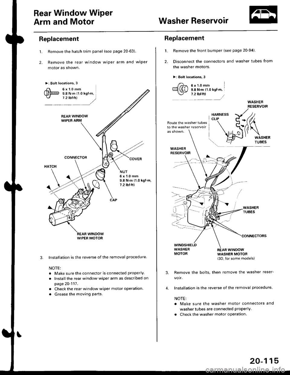
Replacement
't.
2.
Remove the hatch trim panel (see page 20 63).
Remove the rear window wiper arm and wiper
motor as shown.
Installation is the reverse of the removal procedure
NOTE:
. Make sure the connector is connected properly
.Install the rear window wiper arm as described on
page 20-117.
. Check the rear window wiper motor operation.
. Grease the moving parts.
3.
NUT6x1.0mm9.8 N.m 11.0 kgf.m,7.2 tbf.ft)
WIPER MOTOR
L
2.
Replacement
Remove the front bumper (see page 20-94).
Disconnect the connectors and washer tubes from
the washer motors.
>: Bolt locations,3
/)^ 6xt.omm
Ql(S) s.e ru.- tt.o ret '".\./ 7 .2 tbf.ft) /
Route the washer tubes10 the washe. reservoir
wtNDowWASHER MOTOR(3D, for some models)
Remove the bolts, then remove the washer reser-
voir.
Installation is the reverse of the removal procedure.
NOTE:
a Make sure the washer motor connectors and
washer tubes are connected properly.
. Check the washer motor operation.
3.
4.
20-115