1997 HONDA CIVIC engine code
[x] Cancel search: engine codePage 548 of 2189

\
Fue| Tank Pr€ssure sensor 196 Dr6Y8 engine (coupe},,97 D16Y7 angino (coupo: KL mode|' 3edan: KL (Lxl modg||',97
Dl6Y8 engine (coupe: all modeb, sedan: Ki model.'98'all modols) 39 - 0O Dl6Y5 ongins with M/Tl:
rFoG'l::;Jl"too|indicatesDiagnosticTroub|ecode(oTc)P0453;Ahighvo|tageprob|emintheFue|TankPressure
ECM/PCM CONNECTOR D Il6PI
PTANKILT GRNI
\
Wire side of tgmale torminals
FUEL TANKPRESSURE SENSOR3P CONNECTOR (C792)
vcc2(YEL/BLU}
sG2(GRN/BLKI
Wire sid€ of female terminals
I
sG2IGRN/BLKI
PTANKIGBN/RED}
(cont'd)
11-279
The MIL has beon reponed on
DTC P0453 b stored.
Check the vacuum lines:
Check the vacuum lines oI the
fueltank pressure sensor for mis-
routing, leakage, breakage and
clogging.
Are the vacuum lines OK?
Problem verification:1. Do the ECM/PCM Reset Proce-
dure.2. Femove the fuel fill cap
3. Turn the ignition switch oN (ll).
4. Monitor the FTP Sensor volt-
age with the Honda PGM
Tester, or measure voltage
between bodY ground and
ECM/PCM connector termrnal
D15.
lntormittont t iluro, 3Ystem is OK
at this time. Check lot Poor con_
noctiona or loo3e wirat at C131
{loc.ted undor right 3id6 of d8hl,
CaOl llocatod rbov. under-dalh
fus6/relay boxl, C574 (C568lr
llocatod und6l accoss Pan6ll,C792 lfuel tank Preasulo aonlorl
end ECM/PCM.
ls there approx. 2 5 V?
Check for an oPen in the wire(SG2line):1. Turn the ignition switch OFF.
2. Reinstall the fuellill cap
3. Disconnect the fuel tank Pres-sure sensor 3P connector.
4. Turn the ignition switch ON (ll)
5. Measure voltage between the
fuel tank Pressure sensor 3P
connector terminals No. 1 and
No.2.
Ropair opon in the wira b€tw€sn
the fuel tank prasure sonlor and
ECM/PCM (Dl1).ls there aPProx. 5 V?
Check for an open in the wire(PTANK line):Measure voltage between the
fueltank Pressure sensor 3P con-
nector No. 3 terminal and No. 2
termrnal,
ls there approx. 5 V?
*: coupe
{To page 11-280)
Page 550 of 2189

\
'99 - 0O modols except Dl5Y5 engine with M/T:
rFo45'::n":"tooIindicatesDiagnosticTroub|ecode(DTc)P0453:Ahighvo|tageprob|emintheFUelTankPressure
Wire side of temale terminals
FUEL TANKPRESSUNE SENSOR
SUB.HARNESS6P CONNECTOR {C574 (C568)}}
vcc2{YEL/BLUI
sG2IGRN/BLK)
Wire side of female terminals
PTANK{LT GRNI
(cont'd)
11-281
ECM/PCM CONNECTOR A {32P)
PTANK {LT GRN)
The MIL has been reported on.
DTC P0453 is stored.
Check the vacuum lines:
Check the vacuum lines ot the
fuel tank pressure sensor for mis-
routing, leakage, breakage and
clogging.
Are the vacuum lines OK?
Problem verilication:1. Do the ECM/PCM Reset Proce-
du re,2. Remove the fuel fill caP
3. Turn the ignition switch ON (ll).
4. Monitor the FTP Sensor volt'
age with the Honda PGM
Tester, or measure voltage
between body ground and
ECM/PCM connector terminalA.29.
lntermittent failuro. svstem b OK
at this time. Check for Poor con_
noctions or loo3€ wire3 at C131
{located under tight side of dash),
C4Ol {located above underdash
fuse/relay boxl, C57{ (C5681'
llocaled unde. access Panell,C792 {fuel tank Pressure sensorl
aod ECM/PCM.
ls there approx.2.5 V?
Ch€ck for an open in the wira
{SG2line):1. Turn the ignition switch OFF.
2. Reinstall the fuel fill caP
3. Remove the access Panellrom the floor.
4. Disconnect the fuel tank Pres-sure sensor sub-harness 6P
5. Turn the ignition switch ON (ll)
6, At the access Panelside, mea-
sure voltage between the fuel
tank pressure sensor sub_har-
ness 6P connector termlnals
No.5 and No.6.
Repair open in the wire between
the fueliank Pres3ure 3ensor and
ECM/PCM {Cl8).ls there approx.5 V?
Check lor an oPen in the wire
{PTANK linel:At the access Panel side, mea
sure voltage between the fuel
tank pressure sensor suo_harness
6P connector No. 2 terminal and
No. 6 terminal.
ls there approx. 5 V?
(To page 11.282)
Page 552 of 2189

\
t,96 D16Y8 engine (coup6l,'9? Dl6Y7 engine (coupe: KL model, sedan: KL (LX) model)"g7 Dl6Y8 ongine (coupe: all mod-
els, sedan: KL model,'98-8ll modelsl 39 - 00 Dl5Y5 engine with M/Tl:
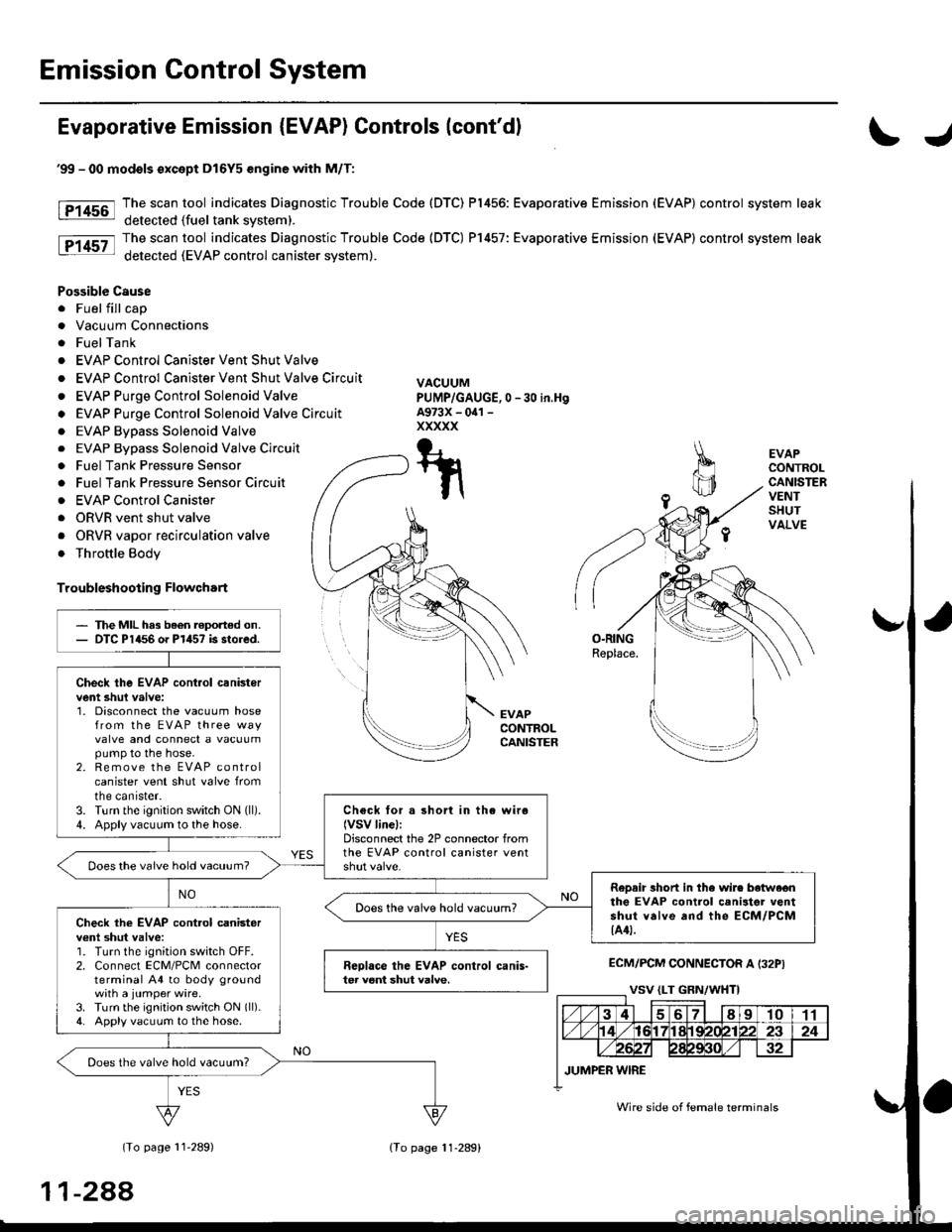
The scan tool indicates Diagnostic Trouble code (DTc) P1456: Evaporative Emission (EVAP) control system leak
detected (fuel tank sYsteml
The scan tool indicates Diagnostic Trouble Code (DTC) P1457: Evaporative Emission (EVAP) control system leak
detected (EVAP control canister system).
Fr4t6l
fF14s7
Possible Causs
. Fuel fill cap
. Vacuum Connections
. Fuel Tank
. EVAP Control Canister Vent Shut Valve
. EVAP Control Canister Vent Shut Valve Circuit
. EVAP Purge Control Solenoid Valve
. EVAP Purge Control Solenoid Valve Circuit
. EVAP Bypass Solenoid Valve
. EVAP Bypass Solenoid Valve Circuit
. Fuel Tank Pressure Sensor
. Fuel Tank Pressure Sensor Circuit
. EVAP Control Canister
. Throttle Body
Troublsshooting Flowchart
VACUUMPUMP/GAUGE,0 - 30 in.HgA973X - 041 -
xxxxx
I
EVAPCONTROL
.4, cANrsrER
re ./ VALVE
{S----r*::n
\(cont'd)
- The MIL ha3 been rePofted
on.- DTC P1456 or P1457 is stored.
Check the EVAP control canbtol
vent shut valve:1. Disconnect the vacuum hose
Irom the EVAP three waY
valve and connect a vacuurnpump to the hose.
2. Remove the EVAP control
canister vent shut valve Irofi
the canrster.3. Turn the ignition switch ON (lli
4. Apply vacuum to the hose.
Chock for . shon in the wire(VSv linel:Disconnect the 2P connector {rom
the EVAP control canister vent
Does the valve hold vacuum?
Repair short in the wir€ betwcen
the EVAP control canister vent
shut v.lve and tho ECM/PCM
tA29|.
Does the valve hold vacuum?
Check the EVAP control canister
vent shui valve:1. Turn the ignition switch OFF.
2. Connect ECM/PCM connectorterminal A29 to body ground
with a iumPer wire.
3. Turn the ignition switch ON (ll).
4. Applyvacuum to the hose
Reohce the EVAP control canis-
ter vent shttt valve.
Does the valve hold vacuum?
ECM/PCM CONNECTOR A {32P)
37I9t01t't2t3t5t6ItItt9202a2a
25aA
ILT GRN/W{T) I JUMPER WIRE
Wire side of femll terminals
(To page 11-284i(To page 11 284)
11-283
Page 557 of 2189

Emission Control System
Evaporative Emission {EVAP) Controls (cont'dl
\J
tF1456-l
tP14sz-l
EVAPCONTROLCANISTERVENTSHUTVALVE
O.RINGReplace.
EVAPCONTROLCANISTER
ECM/PCM CONNECTOR A I32PI
(To page 11'289)
'99 - 00 modols except Dl6Y5 engine with M/T:
The scan tool indicates Diagnostic Trouble Code (DTC) P1456: Evaporative Emission (EVAP) control system leak
detected (fuel tank svstem).
The scan tool indicates Diagnostic Trouble Code (DTC) P1457: Evaporative Emission (EVAP) control system leak
detected (EVAP control canister system).
Possible Cause
. Fuel fill cap
. Vacuum Connections
. FuelTank
. EVAP Control Canister Vent Shut Valve
. EVAP Control Canister Vent Shut Valve Circuit
. EVAP Purge Control Solenoid Valve
o EVAP Purge Control Solenoid Valve Circuit
. EVAP Bypass Solenoid Valve
0 -30 in,Hg
. EVAP Bypass Solenoid Valve Circuit
. Fuel Tank Pressure Sensor
. Fuel Tank Pressure Sensor Circuir
. EVAP Control Canister
. ORVR vent shut valve
. ORVR vapor recirculation valve
. Throttle Body
Troubleshooting Flowchart
VACUUMPUMP/GAUGE,A973X - oal -
xxxxx
T-t
t\
The MIL has been reported on.DTC P1456 o. P1457 is stored.
Check the EVAP cont.ol canistervent shul valve:1. Disconnect the vacuum hosefrom the EVAP three wayvalve and connect a vacuumpump to the hose.2. Remove the EVAP controlcanister vent shut valve fromtne canrster.3. Turn the ignition switch ON (ll).
4. Apply vacuum to the hose.Check for a short in the wiro(VSV linel:Disconnect the 2P connector fromthe EVAP control canister ventDoes the vaive hold vacuum?
RoDair 3hort in the wire botwe€nthe EVAP control canilter ventshut valve and the ECM/PCM{A4t.
Does the valve hold vacuum?Check the EVAP cont.ol canisterv€nl shut valve:1. Turn the ignition switch OFF.2. Connect ECM/PCM connectorterminal A4 to body groundwith a jumper wire.3. Turn the ignition switch ON (ll).
4. Apply vacuum to the hose.
Reolace the EVAP control canis-ter veni shut valve.
Does the valve hold vacuum?
Wire side of female terminals
11-288
lTo page 11-289)
Page 752 of 2189

Electrical Troubleshooting ('96 - 98 Models)
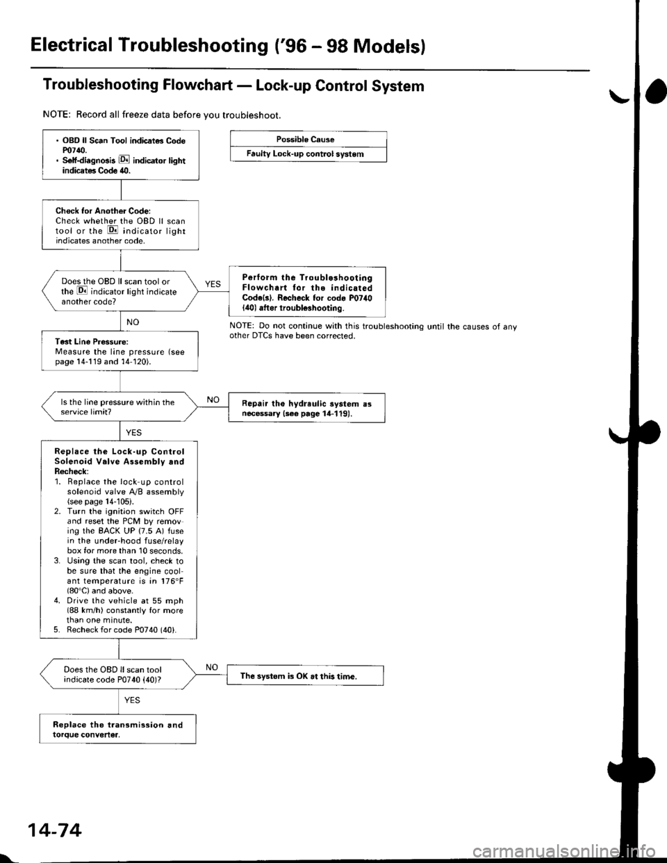
Troubleshooting Flowchart - Lock-up Control System
NOTE: Record all freeze data before vou troubleshoot.
Possible Cause
Faulty Lock-up cont.ol system
NOTE: Do not continue with this troublesnoonnoother DTCS have been corrected.until the causes of any
. OBD ll Sc6n Tool indicatG Codem7{0.. Self-diagnosis E indicator lightindicates Code 40.
Check tor Another Code:Check whether the OBD ll scantool or the E indicato, lightindicates another code.
Perform lhe Troublo3hooiingFlowchart tor the indicatedCode(s). Recheck for cod. P07il0lilol aftor iroubl€3hooting.
Does the OBD ll scan tool orthe E indicator light indicateanother code?
Tast Line Pressure:Measure the line pressure (seepage 14-119 and 14-120).
Repair tho hydreulic aystem a3necessary {3ee page 14-119).
Replace the Lock-up ControlSolenoid Valve Assembly andR6check;1. Beplace the lock up controlsolenoid valve Ay'B assembly(see page 14-105).2. Turn the ignitaon switch OFFand reset the PCM by removing the BACK UP (7.5 A) fusein the underhood fuse/relaybox for more than 10 seconds,3. Using the scan tool, check tobe sure that the engine coolant temperature is in 176'F(80'C) and above.4. Drive the vehicle at 55 mph(88 km/h) constantly for morethan one minute.5. Recheck for code P0740 (40).
Does the OBD ll scan toolindicate code P0740 {40)?The systom k OK at this time.
l'.
14-74
Page 777 of 2189

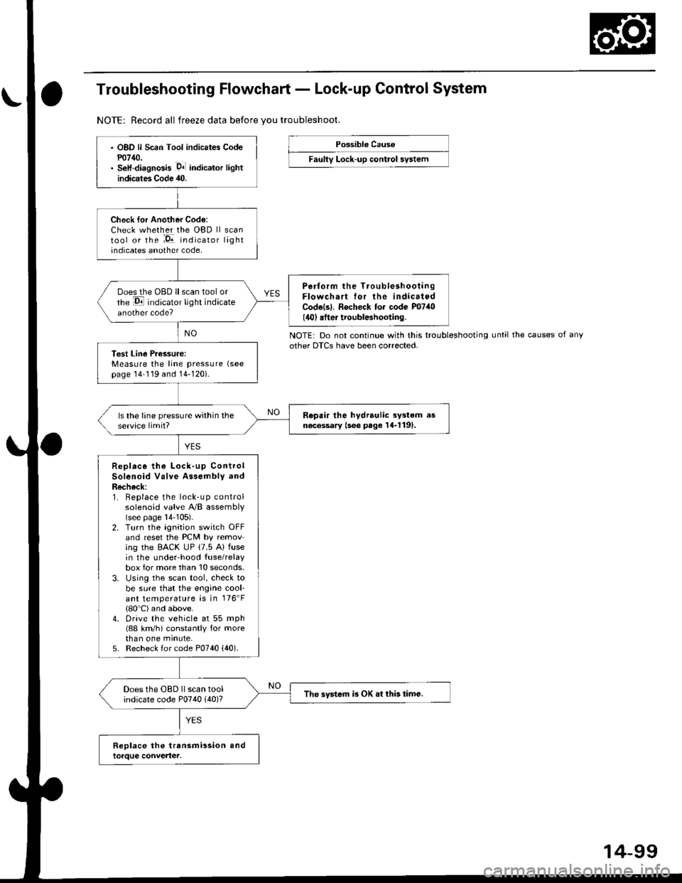
Troubleshooting Flowchart - Lock-up Control System
NOTE: Record all freeze data before vou troubleshoot.
Possibl€ Cause
Faulty Lock-up control sy3tem
NOTE: Do not continue with this troubleshootingother DTCS have been corrected.until the causes of any
OBD ll Scan Tool indicates Codem14/J.S€lf-diagnosis .D4l indicalor lightindicates Code 40.
Check for Another Code:Check whether the OBD ll scantool or the :E indicator lightindicates another code,
Perform the TroubleshootingFlowchart tor the indicatedCodels|. Rocheck to. code P0740(40) .fter troublBhooting.
ooes the OBD ll scan tool orrhe E indicator light indicateanother code?
Test Line Pressure:Measure the line pressure (see
page 14 119 and 14-120).
Repair the hydrrulic sy3tem asn6c6ssary (see page 14-1191.ls the lane pressure within theservice limit?
Replace the Lock-up ControlSolenoid Valve Assembly andRecheck:1. Replace the lock-up controlsolenoid valve A/B assembly(see page 14-105).2. Turn the ignition switch OFFand reset the PCM by removing the EACK UP (7.5 A) fusein the underhood {use/relaybox for more than 10 seconds.3. Using the scan tool, check tobe sure that the engine cool-ant temperature is in 176'F(80'C) and above.4. Drive the vehicle at 55 mph(88 km/h) constantly for morethan one minute,5. Recheck for code P0740 {40).
Does the OBD ll scan toolindicate code P0740 (40)?The svstem i3 OK .t this time.
14-99
Page 906 of 2189

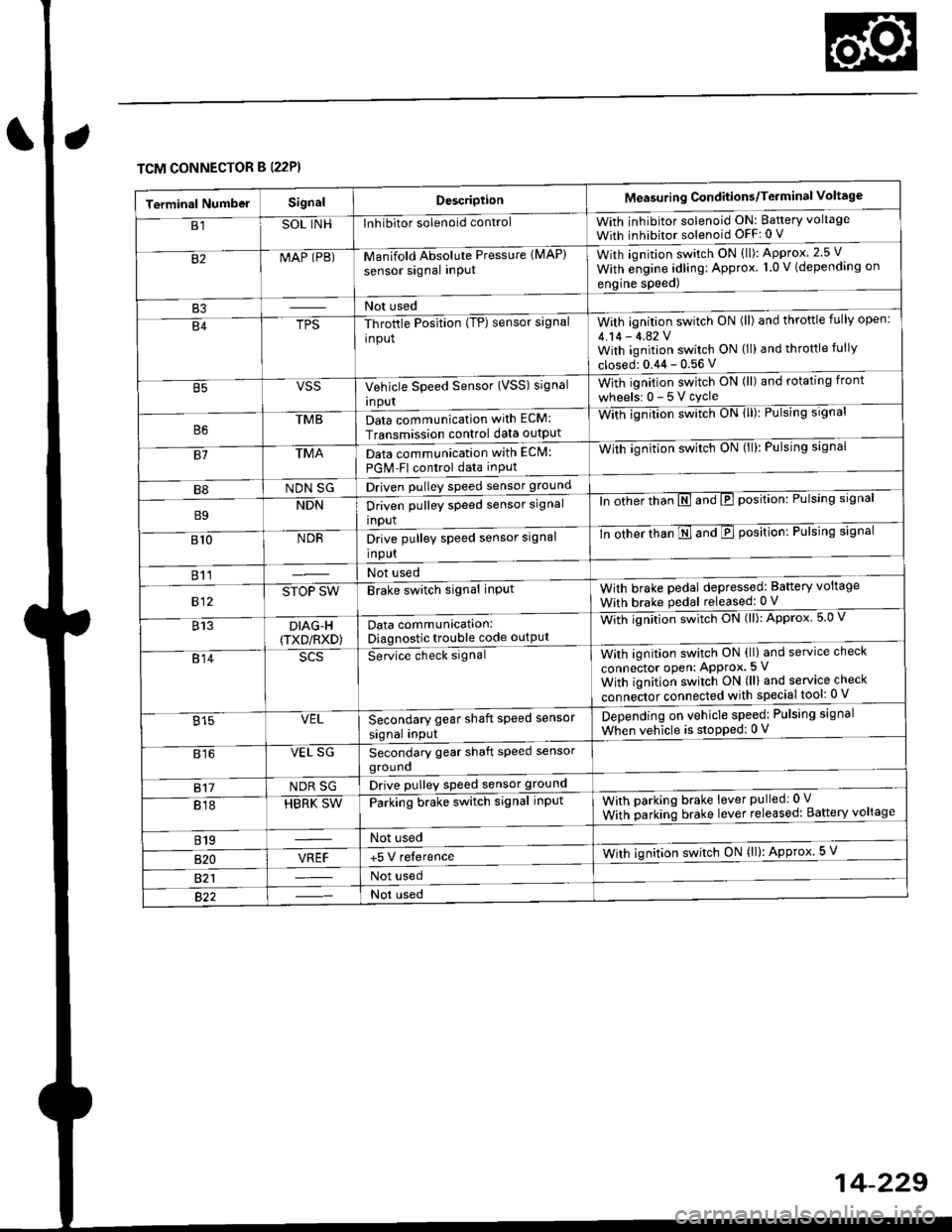
TCM CONNECTOR B (22P}
Terminal NumbelSignalDescriptionMeasuring Conditions/Terminal Voltage
B1SOL INHInhibitor solenoid controlWith inhibitor solenoid ON: Baftery voltage
With inhibitor solenoid OFF: 0 V
82MAP (PB)-M an if old Absol r-rte Pressure IMAP)
sensor signal inPUtWith iqnition switch ON (ll): Approx.2.5 V
With e;gine adling: Approx. 1.0 V (depending on
engine speed)
B3Not used
B4TPS-Throttle Position (TP) sensor signal
input
With ignition switch ON (ll) and throftle fully open:
4.14 - 4.42 VWith ignition switch ON (ll) and throttle fully
closed: 0.44 - 0.56 V
VSSVehicle Speed Sensor (VSS) signal
Inpur
With ignition switch ON (ll) and rotating front
wheelsr 0-5Vcycle
TMBData communication with ECM:
Transmission control data outpUt
With ignilion swltch UN lll): rulslng slgnar
81TMAData communication with EClvl:
PGM Fl control data inPut
With ignition swltch uN {ll,: l-ulslng slgnal
B8NDN SGDriven pulley speed sensor ground
B9NDNDriven pulley speed sensor signal
input
ln other thTnE and E position: Pulsing signal
810NDRDrive pulley speed sensor signal
Input
-tn ottrer ttran E ana E position: Pulsing signal
811Not used
812STOP SWBrake switch signal inPutWith brake pedal depressed: Battery voltage
With brake pedal released: 0 V
813DIAG-H(TXD/RXD)Data communication:Diagnostic trouble code outPut
Wittr ignitio.r s*itct' ON (ll): Approx 5.0 V
814Se-ice ctrect signatWith ignition switch ON (ll) and service check
connector oPen: APProx.5 V
With iqnition switch ON (ll) and service check
"onn"itot. connect"d with special tool: 0 V
Secondary gear shaft speed sensor
signal input
Depending on vehicle speed: Pulsing signal
When vehicle is stoPped: 0 V815VEL
816VEL SGSecondary gear shaft speed sensorgrouno
817NDR SGDrive pulley speed sensor ground
818HBRK SWParking brake switch signal inPutWith parking brake lever pulledr 0 V
With parking brake lever released: Battery voltage
819Not used
B�20VREF+5 V relerenceWith ignition switch ON (ll): Approx 5 V
821Not used
Not used
Page 925 of 2189

Electrical Troubleshooting ('96 - 9g Models)
Troubleshooting Flowchart - lgnition Coil
NOTE: Record all freeze data before you troubleshoot,
Po3rible Cause
. Dbconnected ignition coil con-nectol. Short o. op6n ignition coil wire' F.ulty ignition coil
Wire side ot female terminals
. OBD ll Scan Tool indicates CodePOl25.. Soll-diagnosis E indicarol lightindicates Code 11.
Measure NE Voltrge:1. Disconnect the A {26p) connector from the TCM.2. Start the engine.3. Measure the voltage betweenthe A5 and 413 or A26 termi-nals,
R6p.i. open or short in the wireb€lween the A5 te.minsl and thoignhion coil. It wir€ b OK, checkthe ignition coil test lsoc aoction23t.
ls there battery voltage?
Check for loose TCM connector.It nec$sery. substilute a known-good TCM and .echeck.