Page 1189 of 2189
Rear Drum Brake
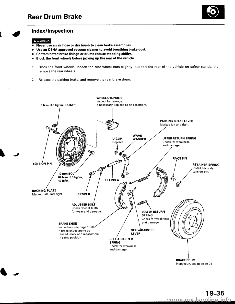
Index/lnspection
'1.
a
a
Never use an air hose or dly brush to clean brake assemblies,
Use an OSHA approved vacuum cleanar to avoid breathing brake dust,
Contaminated brake linings or drums reduce stopping ability.
Block the tront wheels before iacking up ths r€ar of lhe vehicle.
Block the front wheels, loosen the rear wheel nuts slightly, support the rear of the vehicle on safety stands, then
remove the rear wheels.
2. Release the parking brake, and remove the rear brake drum.
I N m 10.9 kgtm, 6.5 lbf.ftl
TENSION PIN
10 mm BOLT6,1N m 15.5 kgf m,47 tbf.ft)
WHEEL CYLINDERInspect for leakage.lf necessary, replace as an assembly.
u-cLrPReplace.
WAVEWASHER
PARKING BRAKE LEVERMarked left and right.
Check for weaknessano oamage,
UPPER RETURN SPRING
I
@JPIVOT PIN
BACKING PLATEMarked lelt and right-
/
€f-l.^
I I
*'t")
ctEv'sB
/ (t
/ ,.ro,".r r.*,"n
/ , Install securely on
| / tension pin.
d"/
IU
ADJUSTER BOI-TCheck ratchet teethfor wear and damage.LOWER RETURNSPRINGCheck for weaknessand oamage.BRAKE SHOEInspection, see page 19-36lf brake shoes are to bereused, mark and reassemblein same position.
SELF.ADJUSTERLEVEB
SELF-ADJUSTERSPRINGCheck for weaknessano oamage.
BRAKE DRUMInspection, see page '19 36
t
19-35
Page 1198 of 2189
Component Locations
ta
SERVICE CHECK CONNECTOR {2PIBIGHT.REAR WHEELSENSOR CONNECTORMOOULATOR UNITABS CONTROL UNIT
RIGHT-REAR WHEEL SENSOR
LEFT.R€AR WHEELSENSOR CONNECTOR
J
UNDER.DASH FUSE/RELAY 8OX
LEFT.FRONT WHEEL SENSOR
ABS +B (20 A) FUSE
UNDER.HOOD FUSE/RELAY BOX
lcl lilo Al FUSE
ABS INDICATOR LIGHT
UNOEF.DASI{ FUSE/RELAY BOX
HORN/STOP I15 A) FUSE
UNDER.HOOO ABS FUSE/RELAY BOX
PUMP MOTOR {'O A} FUSE
PUMP MOTOR BELAY
E
o
METEB I7.5 AI FUSE
0
0
0
00000 n
00000 u
BR DEF RLY 17,5 A) FUSE
t
MTR CHECK (7.5 AI FUSE
19-45
Page 1199 of 2189
Anti-lock Brake System (ABSI
Featu res/Construction
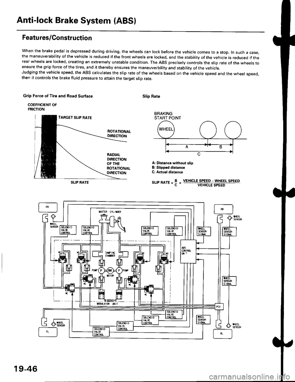
When the brake pedal is depressed during driving, the wheels can lock before the vehicle comes to a stop, In such a case,the maneuverability of the vehicle is reduced if the front wheels are locked, and the stability of the vehicle is reduced if therear wheels are locked, creating an extremely unstable condition. The ABS precisely controls the slip rate of the wheels toensure the grip force of the tires. and it thereby ensures the maneuverbility and stability of the vehicle.Judging the vehicle speed. the ABS calculates the slip rate of the wheels based on the vehicle speed and the wheel speed,then it controls the brake fluid pressure to attain the target slip rate.
Grip Force of Tire and Road Surlace
COEFFICIENT OFFRICTION
TARGET SLIP RATE
Slip Rate
BRAKINGSTART POINT
ROTATIONALDIRECTION
RADIALDIRECTIONOF THEROTATIONALOIRECTION
A: Distance without slio8: Slippsd distanceC: Actuel distance
sr-rrmre=f=SLIP RATEVEIIICLE SPEED - WHEEL SPEEOVEHICLE SPEED
19-46
Page 1204 of 2189
tABS CONIROL UN]TECM / PCMISCS'
V
,,, +-{l-, ?,,] B6li! [,b.,,,,,-F-
SENSOR
+B
YWHTNED
8U(
J-
G,Ol, Ga02
l
\EWIK
LEFT.
RIGHT,
LEFT
;___.|-1
**1. ,I
coierou
SERVICE CHECKCONNECTOR (2P}
lrl2f
OATA LINKCONNECTOR O 6P)
WHEEL SENSOR2P CONNECTOB
FRONT
/.[Ttl\
REAR
tc-T-lI zlr[B'1213
ABS CONTROL UNIT 26P CONNECTOR1O numb€r)
12346/8Il0./ tt12r3
14 t516 1719 ,/2123
-o&"^1'
cot, croz
Terminalside ofmale terminals
ABS CONTROL UNIT 22P CONNECTOR1! numb€r)
/Wire side of female terminals
19-51
Page 1205 of 2189
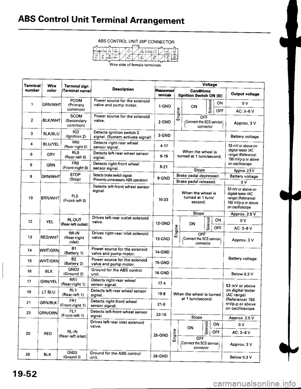
ABS Control Unit Terminal Arrangement
ABS CONTROL UNIT 26P CONNECTOR
Wire side of temale terminals
Terminalnumo0rWirecolorTerminal signTerminalnamoDgscriptionVoltage
Conditions(lgnition Switch ON flt))Output voltagoteminals
PCOM(Primary
common)
Power source for the solenoidvalve and pump motor.1-GNDON
=ONOV
AC: 3-6 V
BLK/WHTscoM(Secondary
common)
Power source for the solenoid
2.GNDOFF
lConnect the SCS service\
conneclor lApprox. 3 V
ELVBLUtG2(lgnition 2)Detects ignition switch 2
!9nal. (system activate signal)3-GNDBatt€ry voltage
BLU/YELRRO(Rear-right 0)Detects right-rear wheelsensor signal.4-17
When the wheel isturned at 1 turn/second.
53 mV or above ondigitaltester (ACra nge) {Fefera nce)150 mvp-p or aboveon oscilloscope
6GRYRLO(Rear-left 0)Detects left-rear wheel sensorsrgnal.6-19
8GRNFRO(Front-right 0)D€tects right-front wheelsgnsor srgnal,a-21StopsApprox.2.5VSTOP(Stop)hects brake switch signal.(Prevents unnecess€ry ABS operation)9-GNDBrake pedal depressed.Battery voltage
Brake pedal released.OV
10BRN^/vHTFLO(Front-left 0)
Detects left-front wheel sensorsignal.
10-23
When the wheel isturned at 1 turn/secono.
53 mV or above ondigitaltester (ACrange) (Referance)
150 mVFporaboveon oscilloscope
9!opsApprox. 2.5 V
12YELRLOUT(Rearjeft outlet)
Drives left-rear outlet solenoid
12.GNDON-9ONOV
OFFAC: 3^6 V
REDMHTRR]N(Rear-right
inlet)
Drives right-rear inlet solenoidvalve.13-GNDOFF
lconnect the SCS service]i connector IApprox. 3 V
14B1(Battery 1)Power source for the solenoidvatve and pump motor.14.GND
Battery voltage15WHT/G R N82(Baftery 2)Power source for the solenoidvarve ano pump motor.15.GND
r6BLKGND2{Ground 2)Ground for the ABS controlunit.16-GNDBelow 0.3 V
17GRN/'/ELRR1(Rear-right 1)Detects right-rear wheelsensor signal.17-4
When the wheel is turnedat 1 turn/second.
53 mV or aboveon digitaltester(AC range)(Referance) 150mVp-p or aboveon oscilloscope
19LT BLURLl(Rea.-left 1)Detects left-rear wheel sensorsagnal.19-6
GRN/BLKFRl(Front-right 1)Detects right-front wheelsensor signal.21-8
FL1(Front-left 1)Detects left-front wheel sensorsignal.23-10StopsApprox. 2.5 V
REDRL-IN(Rear-lett inletl
Drives left-r€ar inlet solenoid
25.GND
ut
ON
'6
-9ONOV
OFFAC: 3-6 V
OFF
lconnect the SCS service] connector lApprox. 3 V
BLKGND3(Ground 3)Ground for the ABS cgntrolunit.26.GNDBelow 0.3 V
19-52
Page 1206 of 2189
e\
t
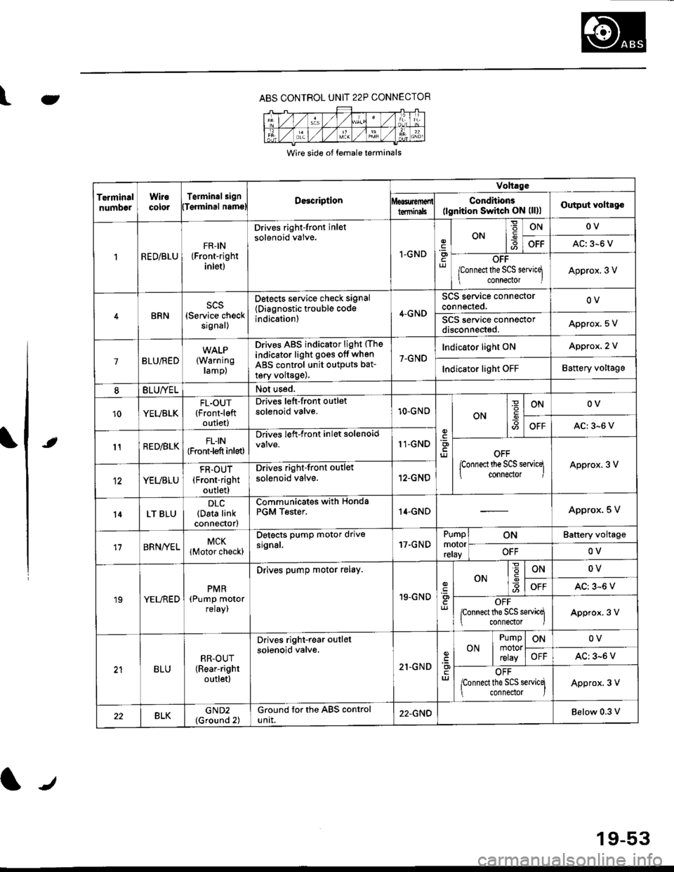
ABS CONTROL UNIT 22P CONNECTOR
Wire side of female terminals
TerminalnumbelWirocororTerminalsignDe3cription
Volt.ge
ConditionE(lgnition Switch ON (ll)lOutput voltagolTqrminal namslterminils
RED/BLUFR-IN{Front-rightinlet)
Drives right-front inletsolenoid valve.
I-GNDriJ
ON-9ONOV
OFFAC: 3-6 V
OFF
/Connect the SCS servicq
connector IApprox. 3 V
BRNscs(Service checksignal)
Detects service check signal
{Diagnostic trouble codeindication)4-GND
SCS service connectorconnected.OV
SCS service connectordisconneded.Appro)(. 5 V
7BLU/RED(Warning
ramp)
Drives ABS indicator light (The
indicator light go€s off when
ABS control unit outputs bat-
tery volta9e),
7-GND
Indicator light ONApprox, 2 V
Indicator light OFFBattery voltage
8BLU/YELNot used.
10YEUBLKFL.OUT{Front-leftoutlet)
Drives left-front outletsolenoid valve.10-GNOON
ONOV
OFFAC:3-6 V
11RED/BLKFLIN{Front-l€ft inlet)
Drives left-front inlet solenoid11-GNDOFF
lconnect the SCS servicq
connector IApprox. 3 V
YEUBLU
FR.OUT(Front-right
outlet)
Drives right-front outlet
solenoid valve.12-GNO
l4LT BLUDLC(Data linkconnector)
Communicates withPGM Tester.Honda14.GNDApprox. 5 V
17BRNA/ELMCK
lMotor check)
Detects pump motor drivesrgnal.17.GNDPumpmotorreray
ONBattery voltage
OFFOV
19YELREDPMR(Pump motorreray,
Drives pump motor relay.
19-GND
ONONOV
OFFAC: 3-6 V
OFFponnect the SCS sewicq
connedor lApprox. 3 V
BLURR-OUT(Rear-right
outletl
Drives right-rear outlel
solenoid valve.
21-GNDuJ
ON
Pumpmotorrelay
ONOV
OFFAC: 3-6 V
OFF
lconnect the SCS servicq
connedor )Approx. 3 V
22BLKGND2(Ground 2)Ground for the ABS controluntt.22-GNDBelow 0.3 v
19-53
Page 1217 of 2189
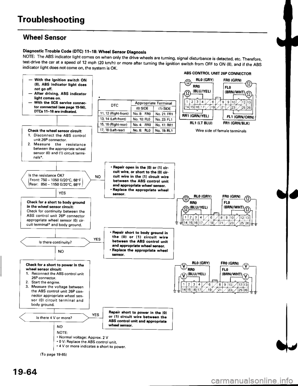
Troubleshooting
Wheel Sensor
Diagnostic Trouble Gode {DTC) ll-18: Wheol S€n3ol DiagnosisNoTE: The ABS indicator light comes on when only the drive wheels are turning, signal disturbance is detected, etc. Therefore,test-drive the car at a speed of 12 mph (20 krn/h) or more after turning the ignition:witch from OFF to ON fll), and if the ABSindicator light does not come on, the svstem is OK.
0TcAppropriate Terminal(0)srDE11) SrD€r 1, 12 (Right-front)No.8: FRoNo.21: FRI13, 14 (Left-front)No. 10: FLoNo.23: FL115, 16 {Right-rear)No. {: RRoNo. 17: RRl17, 18 (Left-rear)No.6: RLoNo. 19: RLI
RLl (LT BLU}FRl (GRN/BLKI
Wire side ol female terminals
NO
NOTE:. Normal voltage: Approx.2 V' 0 V: Replace the ABS controt unit.. 4 V or more indicates a short to power.
A8S CONTROL UNIT 26P CONNECTOR
RRO
IBLU/YELI
RR1 IGRN/YELIFL1 IGRN/ORN}
- With the ignition switch ON{ll), ABS indicator tighr doe.noi go off,- Aftsr driving, ABS indicatotlight comes on.- With the SCS so.vice connac-tor conn€c,ted {soe pege 19-561,DTCs 11-18 a.e indicrted.
Chock lhe wheol sensor ci.cuit:1. Disconnect the ABS controlunit 26P connector.2. lleasure the resistancebetween the appropriate wheelsensor (0) and (1) circuit termi,
. Reprir op€n in the l0l or {0 cir-cuit wiro, or shon to thc {01 cir-cuit wi.o in thc {11 circuit wircbctween ths ABS control unitand approprieto wheel a6nsor.. R.pl.ce th€ epp.opri.te wheal3€nloa.
ls the resistance OK?
/Frontr 750 - 1050 o/20"C, 68.F \\Rear: 850- 1150 O/20.C, 68"F /
Check toru short to body groundin the wheel senso. circuit:Check for continuity between theABS control unit 26P connectorappropriate wheel sensor (0) circuit terminali and body ground.
. Rapair short to body ground inth6 (0) or lll cilcuit wi..bctwa.n th6 ABS control unitand appropdaie whoel lonsor.. Rep|'c6 tho appropriatc whcelsanlor.
Chock tor a sho.t to powe. in thowheel3en3or circuit:1. Reconnect the ABS control unit26P connector,2. Start the engine.3. Measure the voltage betweenthe ABS control unit 26P con-nector appropriate wheel sen-sor (0) circuit terminal andbody ground.
Ropair rhon to powo. in the l0lor lll circuit wire batw.en th€ABS cont.ol unit and .pplopriatawhccl !€naoa,
ls there 4 V or more?
fio page 19-65)
19-64
Page 1229 of 2189
ABS Control Unit
Pulsers/Wheel
Sensors
Replacement
1. Remove the right side kick panel.
2. Disconnect the ABS control unit connecrors.
3. Remove the ABS control unit,
4. lnstall the ABS control unit in the reverse order of
removal,
CONNECTORS
19-76
Inspection
Check the front and rear pulser for chipped or dam-aged teeth.
Measure the air gap between the wheel sensor andpulser all the way around while rotating the pulser.
Slandard: 0.4 - 1.0 mm (0.02 - 0.04 in,
NOTE; lf the gap exceeds 1.0 mm (0.04 in), theprobability is a distorted suspension arm which
should be replaced.
Dbc brake typo
0.{ - 1.0 mm(0.02 - 0.04 in)
Drum brake typ6
1.