1997 HONDA CIVIC For
[x] Cancel search: ForPage 2057 of 2189
Ir
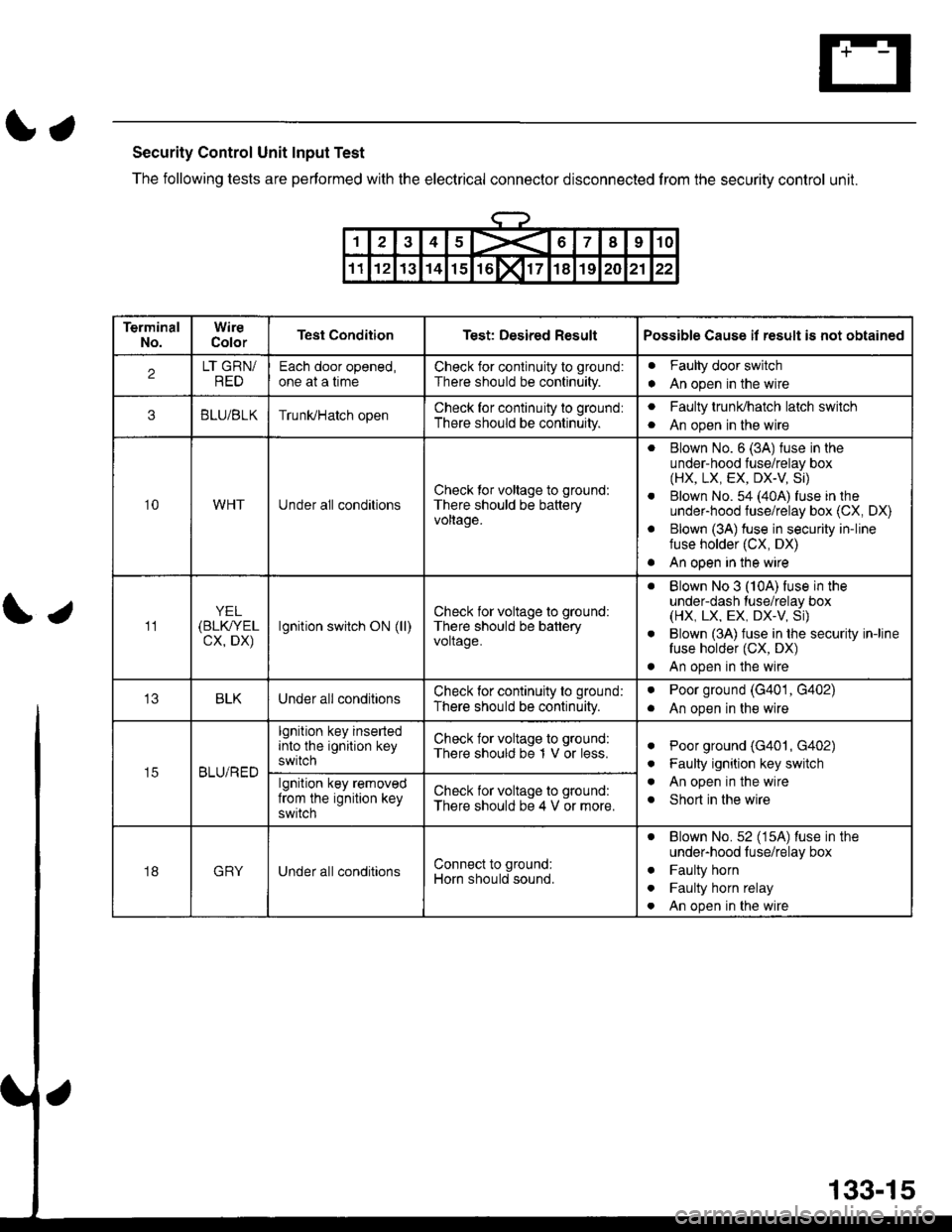
Security Control Unit Input Test
The following tests are performed with the electrical conneclor disconnected from the security control unit.
\;
12345X67I910
1112131415rol171819202122
TerminalNo.WireColorTest ConditionTest: Desired ResultPossible Cause il result is not obtained
2LT GRN/REDEach door opened,one at a timeCheck for conlinuity to ground:
There should be continuity.
Faulty door switch
An open in the wirea
3BLU/BLKTrunUHatch openCheck for continuity to ground:
There should be continuity.
aFaulty trunldhatch latch switch
An open in the wirea
10WHTUnder all conditionsCheck tor voltage to ground:
There should be batteryvoltage.
. Blown No. 6 (3A) fuse in theunder-hood fuse/relay box(HX, LX, EX, DX-V Si)
. Blown No. 54 (40A) fuse in theunder-hood fuse/relay box (CX, DX)
. Blown (3A) fuse in security in-linefuse holder (CX, DX)
. An open in the wire
11YEL(BLK/YEL
cx, DX)lgnition switch ON (ll)Check for voltage to ground:
There should be batteryvoltage.
. Blown No 3 (10A) fuse in theunder-dash tuse/relay box(HX, LX, EX, DX.V, Si)
. Blown (3A) fuse in the security in-linefuse holder (CX, DX)
. An open in the wire
BLKUnder all conditionsCheck for continuity to ground:
There should be continuity.
aPoor ground (G401, G402)
An open in the wirea
t5BLU/RED
lgnition key insertedinto the ignition keyswitch
Check for voltage to ground:
There should be 1 V or less.aPoor ground (G401, G402)
Faulty ignition key switch
An open in the wire
Short in the wire
a
a
algnition key removedfrom the ignition keyswitch
Check for voltage to ground:
There should be 4 V or more.
18GRYUnder all conditionsConnect to ground:
Horn should sound.
. Blown No.52 (15A) luse in theunder-hood luse/relay box
. Faulty horn
. Faulty horn relay
. An open in the wire
133-15
Page 2058 of 2189
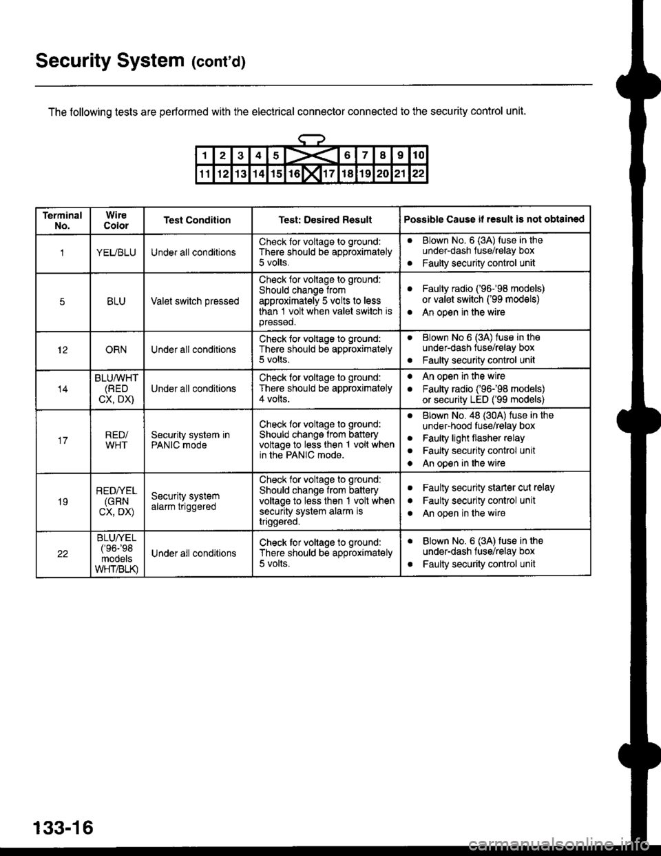
Security System (cont'd)
The following tests are performed with the electrical connector connected to the security control unit.
133-16
TerminalNo.WireColorTest ConditionTest: Desired ResultPossible Cause il result is not obtained
1YEUBLUUnder all conditionsCheck tor voltage to ground:
There should be approximately
5 volts.
aBlown No. 6 (3A) fuse in theunder-dash fuse/relay box
Faulty security control unita
5BLUValet switch pressed
Check tor voltage to ground:
Should change from
approximately 5 volts to less
than 1 volt when valet switch isprsssed.
aFaulty radio ('96-98 models)
or valet switch ('99 models)
An open in the wirea
12ORNUnder all conditionsCheck for voltage to ground:
There should be approximately5 volts.
aBlown No 6 (3A) tuse in tho
under-dash tuse/relay box
Faulty security control unito
14
BLU/WHT(BED
CX, DX)Under all conditions
Check for voltage to ground:
There should be approximately4 volts.
. An open in the wire
. Faulty radio ('96198 models)
or security LED ('99 models)
17RED/WHTSecurity system inPANIC mode
Check for voltage to ground:
Should change from batteryvoltage to less then 1 volt whenin the PANIC mode.
aBlown No. 48 (30A) luse in the
under-hood fuse/relay box
Faulty light flasher relay
Faulty security conlrol unit
An open in the wire
a
a
a
19
REDI/EL(GRN
cx, DX)
Security systemalarm triggered
Check tor voltags to ground:
Should change from batteryvoltage to less then 1 volt whensecurity system alarm istriggsred.
aFaulty security starler cut relay
Faulty security control unit
An open in the wire
I
a
22
BLUA/EL/'oa-'oq
mooelsWHT/BLK)
Under all conditionsCheck tor voltage to ground:
There should be approximately
5 volts.
aBlown No. 6 (3A) fuse in the
under-dash fuse/relay box
Faulty security control unita
Page 2064 of 2189
Security System (cont'd)
3.
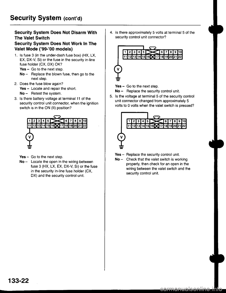
Security System Does Not Disarm With
The Valet Switch
Security System Does Not Work In The
Valet Mode ('99-'00 models)
1. ls fuse 3 (in the under-dash fuse box) (HX, LX,
EX, DX-V, Si) or the fuse in the securily in-line
luse holder (CX, DX) OK?
Yes - Go to the next step.
No - Replace the blown fuse, then go to the
next step.
Does the fuse blow again?
Yes - Locate and reoair the short.
No- Retest the system.
ls there battery voltage al terminal 11 of the
security control unit connector, when the ignition
switch is in the ON (ll) position?
Yes - Go to the next steo.
No - Locate the open in the wiring between
fuse 3 (HX, LX, EX, DX-V, Si) or the luse
in the security inline fuse holder (CX,
DX) and the securiv control unit.
133-22
4. ls there approximately 5 volts at terminal 5 of the
security control unit connector?
Yes - Go to the next steo.
No - Replace the security control unit.
ls the voltage at terminal 5 of the security control
unil connector changed from approximately 5
volts to 0 volts when the valet switch is pressed?
Yes - Replace the security control unit.
No - Check that the valet switch is working
properly, then check for an open in the
wiring between the valet switch and the
security control unit.
Page 2072 of 2189
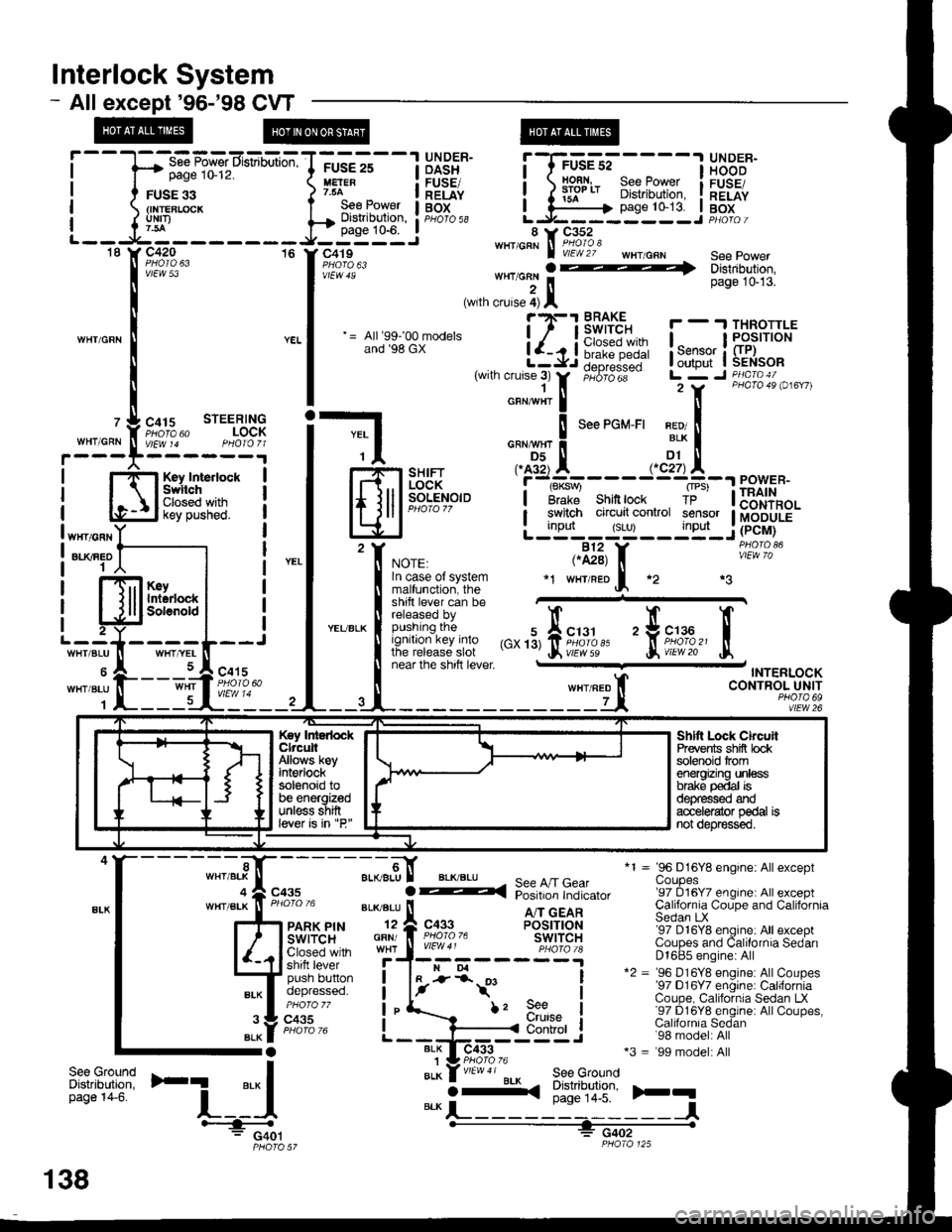
lnterlock System
- Allexcept'96-'98 CVT
page 10-12.
FUSE 33{INTEBLCICKuNrI)
WHIICRN
OASH I HOOD
H:" - IlEiE" i ) iifl* 8i?[',ffii i[".tfi
;GE-st----l glD^:R-
page 10-13. I BoxL.J------ --J PHotoi
*1 = 96 D16Y8 engine: Allexceptuoupes'97 D16Y7 engine: All exceptCalifornia Coupe and CaliforniaSedan LX'97 D16Y8 engine: All exceptCoupes and Calilornia SedanD1685 engine: All*2 = '96 D16Y8 engine: AllCoupes'97 D16Y7 engine: CaliforniaCoupe, California Sedan LX'97 D16Y8 englne: AllCoupes,Calilornia Sedan'98 model: All*3 = '99 model: All
)rq
,'",:[*nu'
=-CF'!,n:E!-l
Hfl*gff* i
l#?;"'" -,,;:::?i-ili:itlll:
|
= lr.u:;.Br-* i-{Ji6i1!-- !,*;L$il{:*
|
,wrn cruse;r
tr,
;"6;dii-- Lr7 r ii\l,B".i o,",,,
i-l o,"*",!
'""'o*-'' x?!
| -$-.",., .^AX-----.,'dtA--"^",."
lfl.iil F]iH*,"'i''t#'---.r=23[11
eowen.
lElJP-".'.'
-
L;tT'#:yTltijF.iu.'f, *or., ,.il3, f, iii"^'?o'
| !^:?::^?l:t:9" *r w'raeof, *2 *3
t:l*ii** ffi"""'"
! fit:'/:,:iffJff ,",'3,fii;1,1,'' 'trii'df,'
tr
I near lne snrn rever - TNTERLOCK
ll wxrneo t CONTROL UNIT
--4-------------Lt, *?,1fl92
T-----1 UNDER-FUSE 25
See Power I BOtDisilibution, : pHb'ro ss
.----
'[il:'ff*,,,,**
., J*:]l ., '"*""
;.-9,[ aL(BLU
GFN/
I
See A/T GearPosition Indicator
A/T GEARPOSITIONswtTcHc433
BLK I-
i-*t'
BLK1BLK
f, 9e€urutse
I
I
I
IControl
ilt:tfi'F1
'-i_:{BLKO-<(
See GroundDistribution,page 14-5.
-l#: G401PHO|O 57
Key IntedockClrcuitAllows keyint€rlocksolenoid tobe energizedunless shiftlever is in "P"
Shltt Lock ChcuilPrevents shifi bcksolenoid tromenergizing unlessbrake p€dal isd€pfessed ardacc€le{ator pedal isnot depr€ssed.
";t-,".f";,
138
Page 2075 of 2189
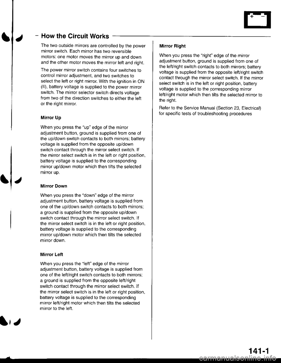
How the Circuit Works
The two outside mirrors are controlled by the power
mirror switch. Each mirror has two reversible
motors: one motor moves the mirror up and down
and the other motor moves the mirror lett and right.
The power mirror switch contains four switches to
control mirror adjustment, and two switches to
select the left or right mirror With the ignition in ON
(ll), battery voltage is supplied to the power mirror
swrtch. The mirror selector switch directs voltage
from two of the direction switches to either the left
or the right mirror.
Mirror Up
When you press the "up" edge of the mirror
adjustment button, ground is supplied from one of
the up/down switch contacts to both mirrors; battery
voltage is supplied from the opposite up/down
switch contact through the mirror select switch. lf
the mirror select switch is in the left or right position,
battery voltage is supplied to the corresponding
mirror uo/down motor which then tilts the selected
mtrror uD.
Mirror Down
When you press the "down" edge of the mirror
adjustment button, battery voltage is supplied Irom
one of the up/down swilch contacts to both mirrors;
a ground is supplied from the opposite up/down
switch contact through the mirror select switch. lf
the mirror select switch is in the left or right position,
battery voltage is supplied to the corresponding
mirror up/down motor which then tilts the selected
mrrror oown.
Mirror Left
When you press the "|eft" edge of the mirror
adjustment button, battery voltage is supplied from
one of the lefuright switch contacts to both mirrors;
a ground is supplied from the opposite lefuright
switch contact through the mirror select switch. lf
the mirror select switch is in the left or right position,
battery voltage is supplied to the corresponding
mirror lefvright motor which then tilts the selected
mirror to the lett.
Mirror Right
When you press the "right" edge of the mirror
adjustment button, ground is supplied from one of
the lefvright switch contacts to both mirrors; battery
voltage is supplied from the opposite left/right switch
contact through the mirror select switch. lf the mirror
select switch is in the left or right position, battery
voltage is supplied to the corresponding mirror
lefuright motor which then tilts the selected mirror to
the right.
Refer to the Service Manual (Section 23, Electrical)
for speclfic tests of troubleshooting procedures
141-1
Page 2077 of 2189
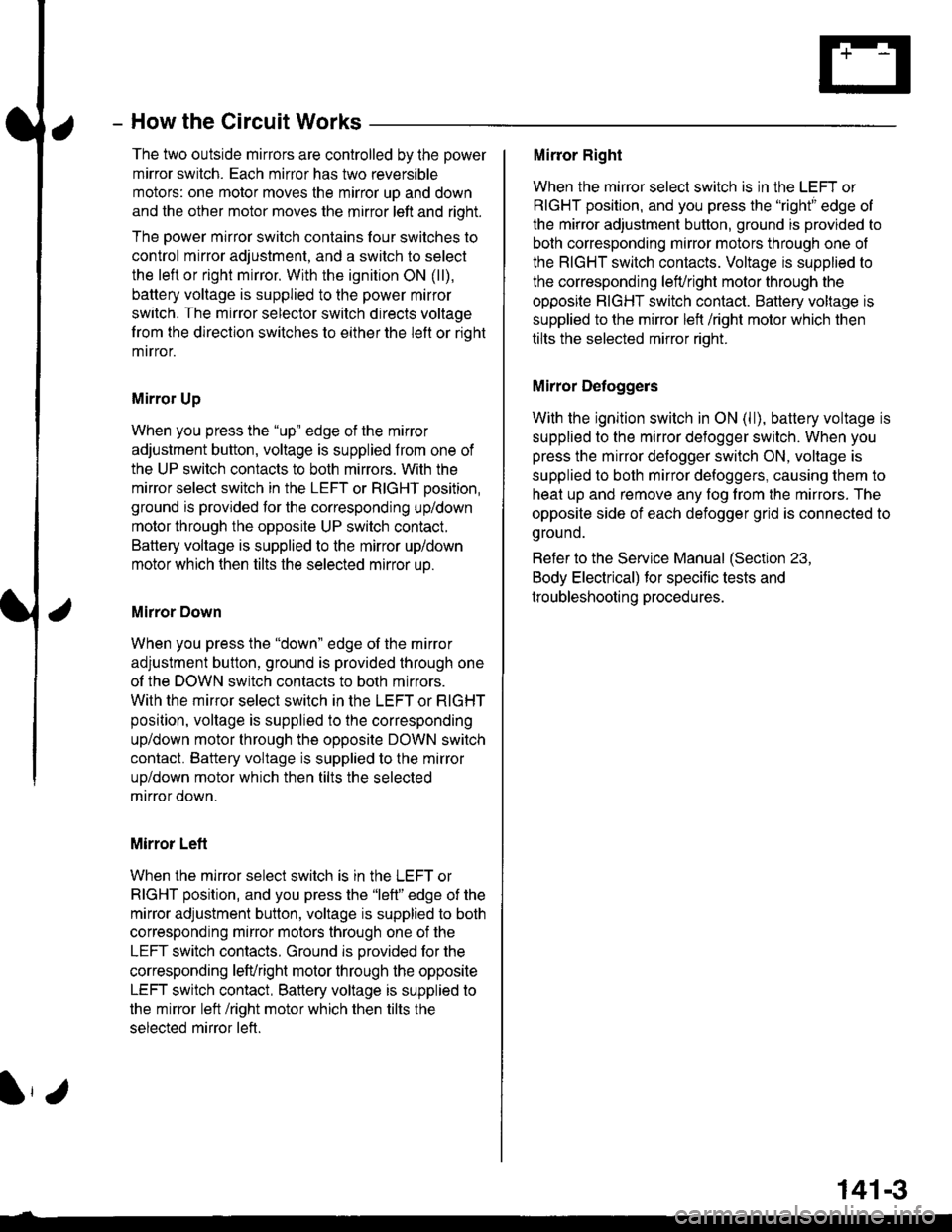
How the Circuit Works
The two outside mirrors are controlled by the power
mirror switch. Each mirror has two reversible
motors: one motor moves lhe mirror uo and down
and the other motor moves the mirror left and right.
The power mirror switch contains four switches to
control mirror adjustment, and a switch lo select
the left or right mirror. With the ignition ON (ll),
battery voltage is supplied to the power mirror
switch. The mirror selector switch directs voltage
Irom the direction switches to either the left or rioht
mtrror.
Mirror Up
When you press the "up" edge of the mirror
adjustment button, voltage is supplied from one of
the UP switch contacts to both mirrors. With the
mirror select switch in the LEFT or RIGHT Dosition.
ground is provjded for the corresponding up/down
motor through the opposite UP switch contact.
Battery voltage is supplied to the mirror up/down
motor which then tilts the selected mirror uo.
Mirror Down
When you press the "down" edge of the mirror
adjustment button, ground is provided through one
of the DOWN switch contacts to both mirrors.
With the mirror select switch in the LEFT or RIGHT
position, voltage is supplied to the corresponding
up/down motor through the opposite DOWN switch
contact. Battery voltage is supplied to the mirror
up/down motor which then tilts the selected
mtrror down.
Mirror Left
When the mirror select switch is in the LEFT or
RIGHT position, and you press the "lett" edge of the
mirror adjustment button, voltage is supplied to both
corresponding mirror motors through one of the
LEFT switch contacts. Ground is provided for the
corresponding lefvright motor through the opposite
LEFT switch contact, 8attery voltage is supplied to
the mirror left /right motor which then tilts the
selected mirror left.
I,J
141-3
Mirror Right
When the mirror select switch is in the LEFT or
RIGHT position, and you press the '?ight" edge of
the mirror adjustment button, ground is provided to
both corresponding mirror motors through one of
the RIGHT switch contacts. Voltage is supplied to
the corresponding leruright motor through the
opposite RIGHT switch contact. Battery voltage is
supplied to the mirror left /right motor which then
tilts the selected mirror right.
Mirror Detoggers
With the ignition switch in ON (ll), battery voltage is
supplied to the mirror defogger switch. When you
press the mirror defogger switch ON, voltage is
supplied to both mirror defoggers, causing them to
heat up and remove any fog from the mirrors. The
opposite side of each defogger grid is connected to
g rou no.
Refer to the Service Manual (Section 23,
Body Electrical) for specific tests and
troubleshooting procedures.
Page 2079 of 2189
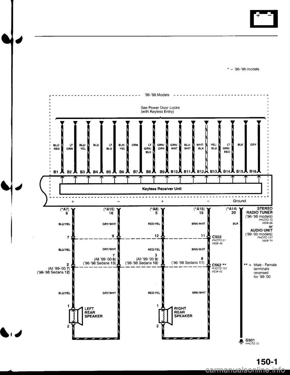
* = 96-98 models
- '96-'98 f'4odels
See Power Door Locks(with Keyless Entry)
LTELU
GFYA!/HT
7(AI'99-'00 6)('96-'98 Sedans l3)
STEREORADIO IUNER('96.�98 models)
vtEw 6aorAUDIO UNIT(99 '00 models)
:l"l:[:I:ilil'
LIGRN/atK
' BLU/I FEO
'81
fA7)
BLU/ryEL
BLU/YEL
rA8)
REO/YEL
(.A14)20
BLK
c503
BED/YEL
(Alt '99-'�00 9)('96-'98 Sedans 10)**= Male- Femaleterminalsreversedfor'99-'00
c562 *2(A
'99-'�00 7)('96-98 Sedans 12)
BLU/YEL
JIG501
150-1
RIGHTREARSPEAKERREARSPEAKER
Page 2111 of 2189
Connector Views (cont'd)
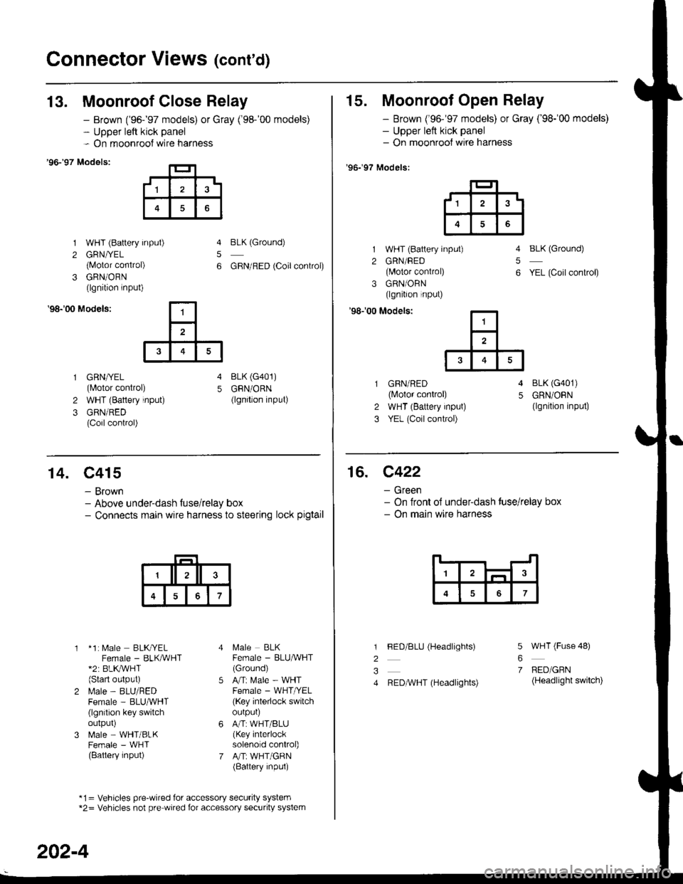
13. Moonroof Close Relay
'96-�97 Models:
1 WHT (Battery input)
2 GRN//EL
{Motor conirol)
3 GRN/ORN(lgnition lnput)
- Brown ('96-'97 models) or Gray ('98-'00 models)- Upper left kick panel- On moonroof wire harness
5
6
BLK (Ground)
GBN/RED (Coilconkol)
'98r00 Models:
GRN/YEL(Motor control)
WHT (Battery input)
GRN/RED(Coil control)
4 BLK (G401)
5 GRN/ORN(lgnition input)2
3
15. Moonroof Open Relay
- Brown ('96-'97 models) or Gray ('98-'00 models)- Upper left kick panel- On moonrool wire harness
'96.�97 Models:
1 WHT (Battery input)
2 GRN/FED(lvlotor control)
3 GRN/ORN(lgnition input)
'98r00 Modelsi
BLK (Ground)
YEL (Coil conkol)
5
6
GBN/RED(lvlotor control)
WHT (Battery input)
YEL (Coil control)
4 BLK (G401)
5 GRN/ORN(lgnition input)2
3
,1^t
6
14. C415
- Brown- Above underdash fuse/relay box- Connects main wire harness to steering lock pigtail
* 1: [,4ale BLKryELFemale - BLKMHT*2: BLK,/WHT(Start oulput)
l\.4ale - BLU/REDFemale - BLUruVHT(lgnilion key switchoutpur)
N4ale - WHT/BLKFemale - WHT(Battery input)
l\,4ale BLKFemale - BLU^VHT(Ground)
Ani Male - WHTFemale - WHT /EL
(Key interlock switchourpur)
A/T:WHT/BLU(Key interlocksolenold control)
A"rT: WHT/GRN(Battery inpul)
*1= Vehicles pre-wired for accessory security system*2= Vehicles not pre wired for accessory security system
202-4
16. C422
- Green- On tront ol under-dash tuse/relay box- On main wire harness
7
l
2
3
4
5
6
7
FED/BLU (Headlights)
REDAVHT (Headlights)
WHT (Fuse 48)
BED/GRN(Headlight switch)