Page 1375 of 2189

Heater
lllustrated Index
'96 - 98 Models ................................ 21'2
'99 - 00 Models ................................ 21'3
Circuit Diagram
'96 - 98 Models .....21-4
'99 - 00 Models ................................ 21-5
Troubleshooting - '96 - 98 Models
Symptom Chart ............................... 21-6
Heater Control Panel Input/
Output Signals ..............,.............. 21-7
Flowcharts
Blower Motor Speed ................... 21-8
Bf ower Motor ,...21'10
Mode Control Motor ............... ,.'.' 21-13
Recirculation control Motor ....... 21-16
Heater Control Panel ................ ... 21 -14
Troubleshooting - '99 - 00 Models
Symptom Chart ............................... 21-19
Seff-diagnosis Function ............,,,.... 21-20
Flowcharts
Air Mix Control Motor ......,.......... 21-21
Mode Control Motor ............... ..... 21 -25
Recirculation Control Motor ....... 21-27
Bf ower Motor Speed .............. .....21'29
Bf ower Motor ....21-31
Heater Control Panel ................,.. 21-35
Heater Control Panel Input/
Output Signals ............................. 21-36
Blower Unit
Repf acement .........21-37
Overhaul ................ 21-38
* Heater Unit
Replacement ....'....21-39
overhaul """" """' 21-4'l
Heater Control Panel
Repfacement .........21'42
Overhaul -'96 - 98 Models ........... 21-43
Temperature Control
Adjustment - '96 - 98 Models """" 21-44
Adiustment - '99 - 00 Models .......21-45
Air Mix Control Motor
Test - '99 - 00 Models ...........' .......21'46
Replacement - '99 - 00 Models ....21'46
Mode Control Motol
Test ................, .,...'.21'47
Replacement '.'."...21-47
Recirculation Control Motor
Test ................. .......21-48
Repf acement ......." 21-48
Relays
Test ................. .......2'l-49
Heater Fan Switch
Test - '96 - 98 Models ............. .......21-49
Mode Control Switch
Test -'96 - 98 Models ..........."....... 21-50
Power Transistor
Test - '99 - 00 Models ....'........ ....".21-50
*: Read SRS Drecautions before working in this area.
Page 1376 of 2189
lllustrated Index
'96 - 98 Models
SRS components are located in this area. Review the SRS component locations, precautions, and procedures in the SRS
section {24) before performing repairs or service.
BLOWER UNITReplacement, page 21-37Overhaul, page 21-38
HEATER UNITBeplacement, page 21-39Overhaul, page 21-41BLOWERRESISTOBTest,
CONTROL MOTORTest, page 21-48Replacement, page 21'48
a/c swtTcH{wirh A/c)
MOO€MOTORTest, page 21 47Replacement, page 21'47
AIR MIX CONTROL CABLEAdjustment, page 2'1-44Replacement, page 21'43
HEATER FANswtTcHTest, page 2l'49
MODEHEATER CONTBOLPANELswrTcHEsTest, page 21 50Rgplacement, page 2'l-42Overhaul, page 21-43
TEMPERATURE CONTROLLEVERAdiustment, page 21 44
Detroster-aqtivated A/C System
Turning the defroster on activates the A,/C and sets the air flow mode to FRESH. lt is possible to turn the A,/C off or to
change the air flow to RECIRCULATE by pressing the A/C bunon or the FRESH/RECIRCULATE button.
21-2
Page 1377 of 2189
'99 - 00 Models
SRS components are located in this area, Review the SRS component locations, precautions, and procedures in the SRS
section (24) betore perfoming repairs or service.
HEATER UNITReplacement, page 21'39
Overhaul, page 21-41
BLOWEB UNITReplacement, page 21-37Overhaul, page 21 38
HEATER FANswtTcH
RECIRCULATIONCONTROL MOTORTest, page 21-48Beplacement, page 21-48
AIR MIX CONTROL MOTOBTest, page 21-46Replacement, page 21 46
BLOWERTest, page 21-49
POWER TRANSISTORTest, page 21 50
HIGH RELAY
MODE CONTROLDIALHEATER VALVE CABLEAdjustment, page 21 45TEMPERATURE CONTROLDIALAdjustment, page 21-45
REAR WINDOWDEFOGGERswtrcHSee section 23MODEMOTORTest, page 21 47Replacement, page 2 l-47A/C SWTTCH
lwith A/cl
CONTROL SWITCH
21-3
Page 1412 of 2189
Blower Unit
Overhaul
NOTE:
RECIRCULATIONCONTROL MOTORTest, page 21-48
aBefore reassembly. make sure that the recirculation control door and linkage move smoothly without binding.
When attaching the recirculation control motor, make sure its positioning will not allow the recirculation control door
to be pulled too far.
After aftaching the recirculation control motor, connect power and ground, and watch the movement of the recircula-
tion control door.
BLOWERTest, page 2'l 9{'96 - 98 modebl
POWER TRANSISTOR l'99 - 00 modeblTest, page 21-50
Test, page 21'10 ('96 98 models) orpage 21'31 ('99 00 models)
m
MOTOR
2134
Page 1422 of 2189

Recirculation Control Motor
Test
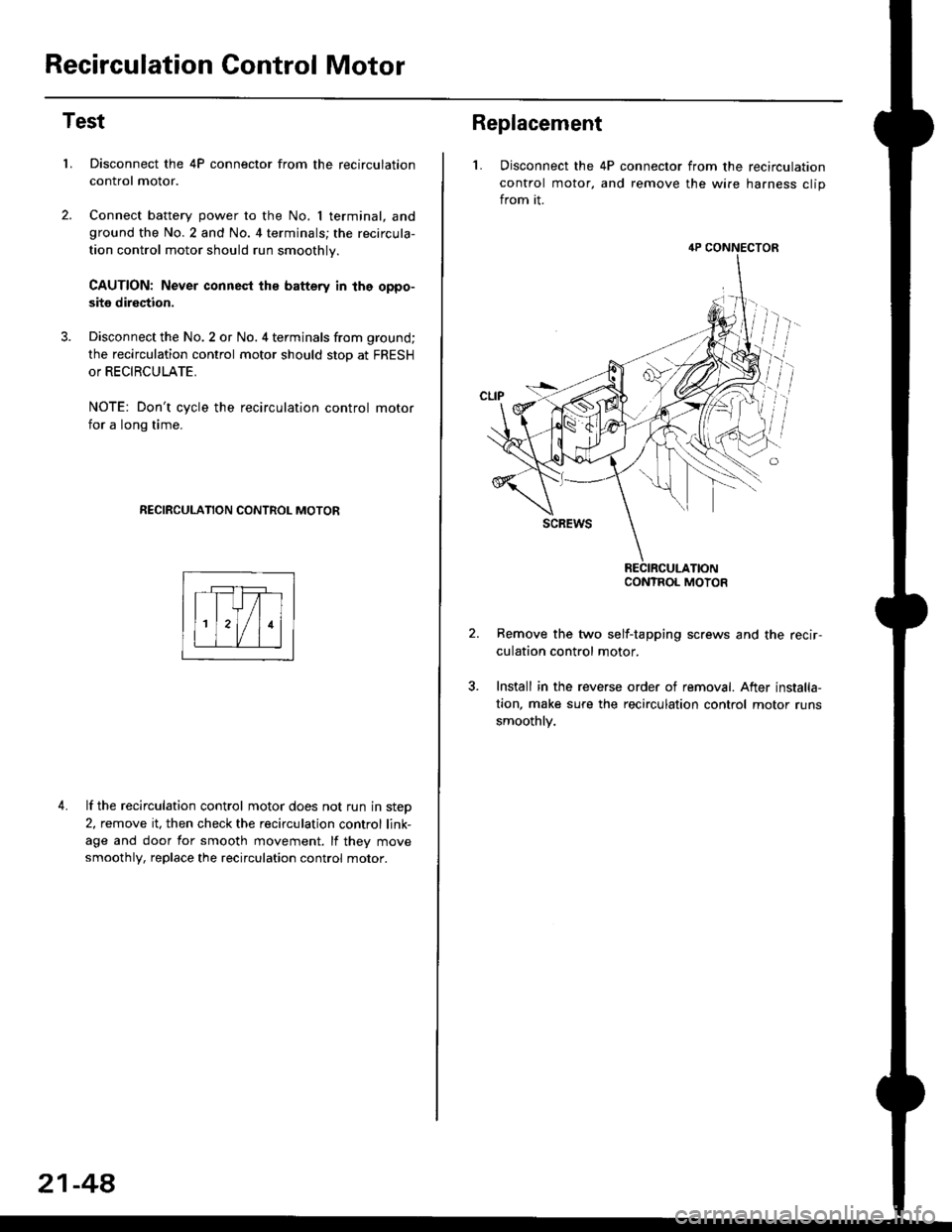
LDisconnect the 4P connector from the recirculation
control motor.
Connect battery power to the No. I terminal, andground the No.2 and No. 4 terminals; the recircula-
tion control motor should run smoothly.
CAUTION: Never connest ths battery in the oppo-
site direction.
Disconnect the No. 2 or No. 4 terminals from ground;
the recirculation control motor should stop at FRESH
or RECIRCULATE.
NOTE: Don't cycle the recirculation control motor
for a long time.
RECIRCULATION CONTROL MOTOR
4. lf the recirculation control motor does not run in step
2, remove it, then check the recirculation control link-
age and door for smooth movement. lf they move
smoothly, replace the recirculation control motor.
21-48
Replacement
L Disconnect the 4P connector from the recirculation
control motor, and remove the wire harness clip
from it.
Remove the two self-tapping screws and the recir-
culation control motor.
Install in the reverse order of removal. After installa,
tion, make sure the recirculation control motor runs
smoothly.
4P CONNECTOR
CONTROL MOTOR