Page 583 of 2189
MaintenanceBack-up Light Switch
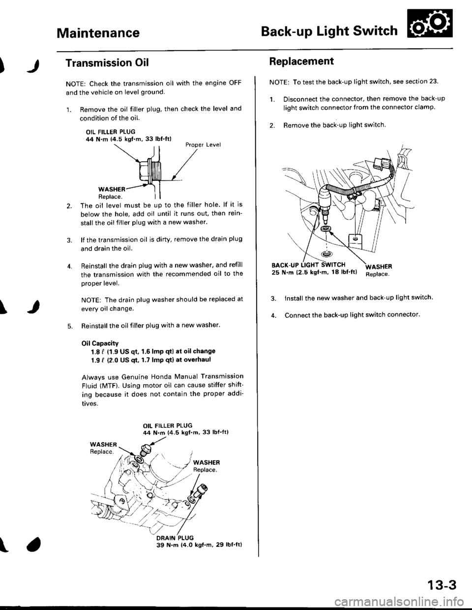
Transmission Oil
NOTE: Check the transmission oil with the engine OFF
and the vehicle on level ground.
1. Remove the oil filler plug, then check the level and
condition of the oil.
OIL FILLER PLUG/14 N.m (4.5 kgl.m,33 lbl.ft)Proper Level
4.
WASHERReplace.
The oil level must be up to the filler hole. lf it is
below the hole, add oil until it runs out. then rein-
stall the oil filler plug with a new washer.
lf the transmission oil is dirty, remove the drain plug
and drain the oil.
Reinstall the drain plug with a new washer, and refill
the transmission with the recommended oil to the
proper lever.
NOTE: The drain plug washer should be replaced at
every oil change.
Reinstall the oil filler plug with a new washer.
OilCapacity
1.8 f (1.9 US qt. 1.6 lmp qtl at oil change
1.9 { (2.0 US $, 1.7 lmp qt) at overhaul
Always use Genuine Honda Manual Transmission
Fluid {MTF). Using motor oil can cause stiffer shift-
ing because it does not contain the proper addi-
t|ves.
\
\
Replacement
NOTE: To test the back-up light switch, see section 23
1. Disconnect the connector, then remove the back-up
light swirch connector from the connector clamp.
2. Remove the back-up light switch.
25 N.m (2.5 kgf'm, 18lbf'ltl
Install the new washer and back-up light switch
Connect the back-up light switch connector.
ASHER
13-3
Page 586 of 2189

Transmission Assembly
Removal (cont'dl
8. Remove the driveshafts (see section 161.
NOTE: Coat all the precision finished surfaces with
clean engine oil or grease. Tie plastic bags over the
driveshaft ends,
DRIVESHAFT
10 x 1.25 mrn43 N.m 14.4 kgt.m,32 rbf.frl
COTTER PINReplace. SELF12 x 1.25 mm49-59 N.m (5.0 -6.0 kgt.m,36-43 lbf.ft)
9. Remove exhaust pipe A.
Replace.12 x 1.25 mm64 N.m {6.5 kgt.m,47 lbf.tr)
GASKETSReplace.
IF\sELF-LocKtNG NUT.''1/Replace.8 x 1.25 mm16 N.m {1.6 kgf'm,12 tbf.ft)
EXHAUSTPIPE A
SELF-LOCKING NUTReplace.I x 1.25 mm22 N.m (2.2 kgf.m,16 tbt'fr)
SELF-LOCKING NUTReplace.D16Y5, D16Y7 engines:
33 N.m {3.4 kgf.m,25 lbt.ft)D16YB engine:10 x 1.25 mm54 N.m 15.5 kgl'm,40 lbf.ttl
SET RING
13-6
v'10. Remove the shift rod and extension rod.
SI'IIFT BOD
8x22mmSPRING PINReplace.
EXTENSION ROD
PIN PUNCH, 8.O mm(Commercially available)f-
'1'1. Remove the engine stiffeners and clutch cover.
D16Y5, D16Y8 engines:
10 x 1.25 mm44 N.m (4.5 kgt.m,33 tbf.tr)
I x 1.25 mm24 N.m (2.4 kgf.m17 lbt.frl
COVER
8 x 1.25 mm24 N.m 12.4 kgf'tn,17 tbt.tr)
Page 587 of 2189
12.
D16Y7 engine:
ENGINESTIFFENER
10 X 1.25 mmIt4 N'm (4.5 kqf'm,33 lbf'ltl
Install the bolts in the cylinder head and attach a
chain hoist to the bolts, then lift the engine slightly
to unload the engine and transmission mounts.
CHAIN HOIST
13. Remove the sDlash shield,
\
8 x 1.25 mm24 N.m {2.4 kgl.m,
SPLASH SHIELD
14. Remove the right front mounvbracket.
'lO x 'l.25 mm44 N'm (4.5 kgl.m,33 rbf.frl
Replace.12 x 1.25 mm
64 N.m t6.5 kgf.m,47 lbf'ft)
Place a jack under the transmission.
Remove the transmission mount bracket and mount.16.
TRANSMISSIONMOUNTTRANSMISSIONBRACKET
(cont'd)
13-7
Page 588 of 2189
Transmission Assembly
Removal(cont'd)
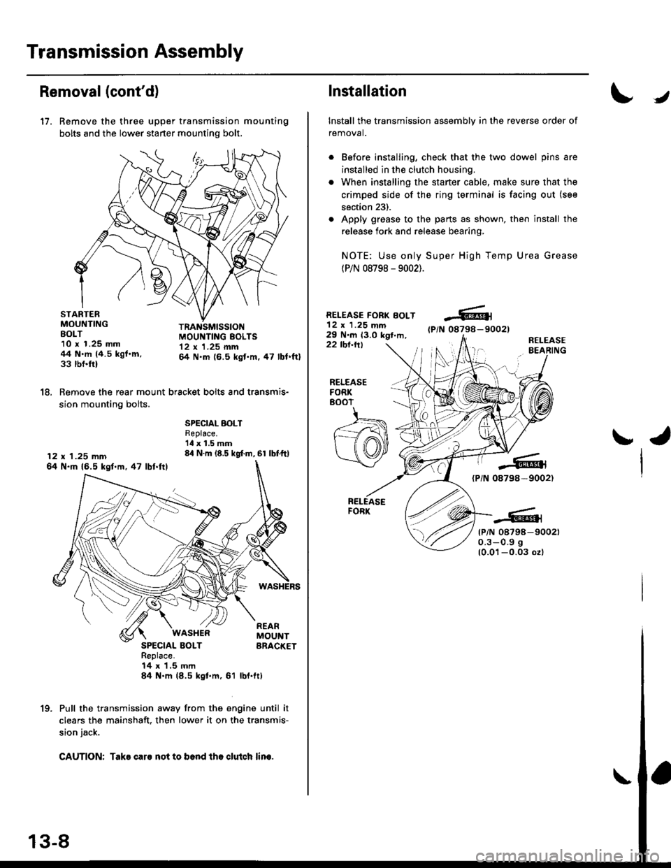
17. Remove the three upper transmission mounting
bolts and the lower starter mounting bolt,
STARTERMOUNTINGBOLT10 x 1.25 mm44 N.m (4.5 kgf.m,33 rbnftl
TRANSMISSIONMOUI{TING EOLTS12 x 1.25 mm& N.m (6.5 kgt'm,47 lbl.ftl
18. Remove the rear mount bracket bolts and transmis-
sion mounting bolts.
12 x 1.25 mm64 N.ft 16.5 kgl.m,47 lbl.ftl
SPECIAL BOLTReplace.'ll x 1.5 mm84 N.m (8.5 kgf.m, 61 lbf.ftl
SPECIAL BOLTReplace.14 x 1,5 mln84 N.m (8.5 kgl.m, 61
WASI{ERREARMOUNTBRACKET
rbl.ftt
Pull the transmission away from the engine until it
clears the mainshaft. then lower it on the transmis-
sion jack.
CAUTION: Take caro not to b6nd tho clutch lin€.
1(|
Installation
Install the transmission assembly in the reverse order of
removal.
Before installing, check that the two dowel pins are
installed in the clutch housing.
When installing the starter cable, make sure that the
crimped side of the ring terminal is facing out (see
section 23).
Apply grease to the parts as shown, then install the
release fork and release bearing,
NOTE: Use only Super High Temp Urea Grease
(P/N 08798 - 9002).
RELEASE FORK BOLT12 x 1.25 mm29 N'm 13.0 kgt,m,(P/N 08798-90021
22 tbl.ttlR€LEASEBEARING
J
RELEASEFORK8()07
ra
{PiN 08798-9002)
tP/N 08798-900210.3-0.9 g
10.01-0.03 ozl
Page 613 of 2189
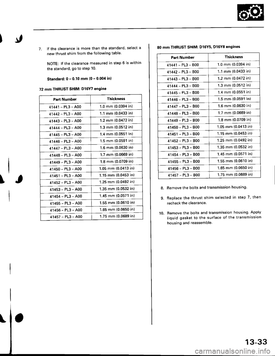
7. lf the clearance is more than the standard, select a
new thrust shim from the following table
NOTE: It the clearance measured in step 6 is within
the standard. go to step 10.
Standard: 0 - 0.10 mm l0 - 0.00/t inl
72 mm THRUST SHIM: D16Y7 engin€
\
Part NumberThickness
41441 - PL3 - A001.0 mm (0.0394 in)
41442-PL3-A00'1 .1 mm {0.0433 in)
41443-PL3-A001.2 mm {0.0472 in)
41444-PL3-A001.3 mm (0.0512 in)
41445-PL3-A001.4 mm (0.0551 in)
41446-PL3-A001.5 mm (0.0591 in)
41447-PL3-A001.6 mm (0.0630 in)
41448-PL3-A001.7 mm (0.0669 in)
4r449-PL3-A001.8 mm (0.0709 in)
41450-PL3-A001.05 mm {0.0413 in)
41451-PL3-A001.15 mm (0.0453 in)
41452-PL3-A001.25 mm (0.0492 in)
41453-PL3-A001.35 mm (0.0532 in)
41454-PL3-A00'1.45 mm (0.057'l in)
41455-PL3-A001.55 mm (0.0610 in)
41456-PL3-A001.65 mm (0.0650 in)
41457-PL3-A001.75 mm (0.0689 in)
80 mm THBUST SHIM: D16Y5. D16Y8 engines
Remove the bolts and transmission housing.
Replace the thrust shim selected in step 7, then
recheck the clearance.
Remove the bolts and transmission housing. Apply
liquid gasket to the surface of the transmission
housing and reassemble
8.
9.
10.
Part NumbelThickness
41441 - PL3 - B001.0 mm (0.0394 in)
41442-PL3-8001.1 mm (0.0433 in)
41443-PL3-8001.2 mm (0.0472 in)
41444-PL3-8001.3 mm (0.0512 inl
41445-PL3-8001.4 mm (0.0551 in)
41446-PL3-8001.5 mm (0.0591In)
41447-PL3-8001.6 mm (0.0630 in)
4r 448 - PL3 - 8001.7 mm (0.0669 in)
4 t449 - PL3 - 8001.8 mm (0.0709 in)
41450-PL3-800'1.05 mm (0.0413 in)
41451 - PL3 - 800'1.15 mm (0.0453 in)
41452-PL3-8001.25 mm (0.0492 in)
41453-PL3-B001.35 mm (0.0532 in)
41454-PL3-B001.45 mm (0.0571 in)
41455-PL3-B001.55 mm (0.0610 in)
41456-PL3-8001.65 mm (0.0650 in)
41457-PL3-8001.75 mm {0.0689 in)
Page 615 of 2189
Cou ntershaft
1. Remove the needle bearing using the special tool as
shown. then remove the oil guide plate
3/g " -16 SLIDE HAMMER
{Commercially available)
PULLER, 25-40 mm07736-AO1000A
\
2. Install the oil guide Plate, then
bearing into the clutch housing
tools as shown.
d rive the needle
using the special
'1: ATTACHMENT, 42 x 47 mm
07746-0010300*2: ATTACHMENT, 52 x 55 mm
07746 -0010400
ORIVER07749 -0010000
CLUTCHHOUSING
NEEOLE BEAFING
GUIDE PLATE
NEEOLE BEARING
*1: D16Y7 enqine*2: D16Y5, D16Y8 engines
OIL GUIDE PTATE
13-35
Page 616 of 2189
Mainshaft Thrust Shim
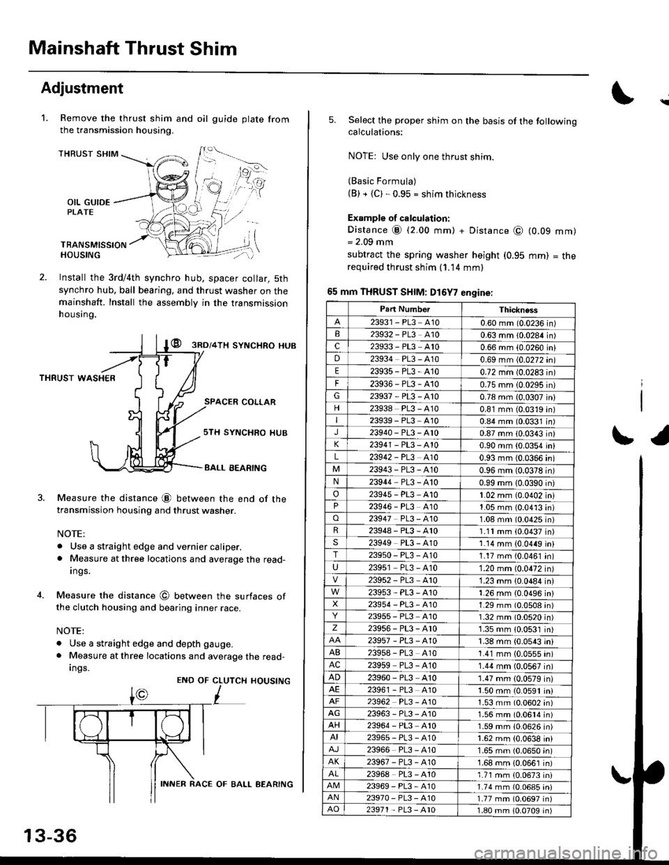
Adjustment
Remove the thrust shim and oil
the transmission housing.
1.gu ide plate from
THRUST SHIM
OIL GUIDEPLATE
TBANSMISSIONHOUSING
Install the 3rd/4th synchro hub, spacer collar, 5th
synchro hub, ball bearing, and thrust washer on themainshaft. Install the assembly in the transmission
h ousing.
@ gnol+lx syNcHRo HUB
THRUST WASHER
SPACER COLLAR
4.
Measure the distance @ between the end of thetransmission housing and thrust washer.
NOTE:
. Use a straight edge and vernier caliper.. Measure at three locations and average the read-
Ings.
Measure the distance @ between the surfaces ofthe clutch housing and bearing inner race.
NOTE:
. Use a straight edge and depth gauge.
. Measure at three locations and average the read-
Ings.
sTH SYNCHRO IIUB
BALL EEARING
CLUTCH
L
HOUSINGENO OF
13-36
INNER RACE OF BALL AEARING
\
5.Select the proper shim on the basis of the followingcalculations:
NOTE: Use only one thrust shim.
(Basic Formula)(B) + {C). 0.95 = shim thickness
Example of calculation:
Distance @ (2.00 mm) + Distance @= 2.09 mm
subtract the spring washer height (0.95
required thrust shim (1.14 mm)
65 mm THRUST SHIM: D16Y7 engine:
(0.09
mm)
mm)
= tne
r1
Part NumborThickness
23931 - PL3 A100.60 mm (0.0236 in)23932 - PL3 A100.63 mm 10.0284 in)c23933 - PL3 A100.66 mm {0.0260 iniD23934 PL3 - A100.69 mm (0.0272 in)
E23935-PL3-4100.72 mm 10.0283 in)
F23936-PL3-4100.75 mm 10.0295 in)G23937-PL3-A100.78 mm {0.0307 in}
23938 PL3 - A100.81 mm (0.0319 in)I23939 - PL3 At00.84 mm (0.0331 in)J23940-PL3-Ar00.87 mm (0.0343 in)
23941 - PL3 - A100.90 mm (0.0354 in)
L23942 - PL3 A100.93 mm (0.0366 in)
23943-PL3-A100.96 mm (0.0378 in)N23944 PL3 - A100.99 mm 10.0390 in)
o23945-PL3-A101.02 mm {0.0402 in}23946 - PL3 A101.05 mm (0.0413 in)o23947 PL3 - 4101.08 mm (0.0425 in)R23948-PL3-A101.11mm (0.0437 in)s23949 PL3 - A101.14 mm {0.0449 in}T23950-PL3-A101.17 mm (0.0461 in)
U23951 PL3 - A101.20 mm (0.0472 in)
23952-PL3-Ar01.23 mm {0.0484 in)
23953-PL3-A101.26 mm {0.0496 in}X23954 - P13, A101.29 mm (0.0508 in)23955 - PL3 A101.32 mm (0.0520 in)z23956-PL3-Ar01.35 mm {0.0531 in)
23957-PL3-A101.38 mm (0.0543 in)
AB239s8 - PL3 A101.41 mm (0.0555 in)AC23959 PL3 - A101.44 mm (0.0567 in)
AD23960 - PL3 A101.47 mm (0.0579 in)23961 - PL3 4101.50 mm (0.0591 in)23962 PL3 - A101.53 mm (0.0602 in)AG23963-PL3-4101.56 mm (0.0614 in)AH23964 - PL3 A101.59 mm (0.0626 in)AI23965-PL3-A101.62 mm {0.0638 in)
23966 PL3 - A101.65 mm (0.0650 in)AK23967-PL3-A101.68 mm {0.0661 in)
23968 PL3 - A101.71 mm {0.0673 in)23969-PL3-A101.74 mm (0.06a5 iniAN23970- PL3 -A101.77 mm (0.0697 in)AO23971 - PL3 - A101.80 mm 10.0709 in)
Page 627 of 2189
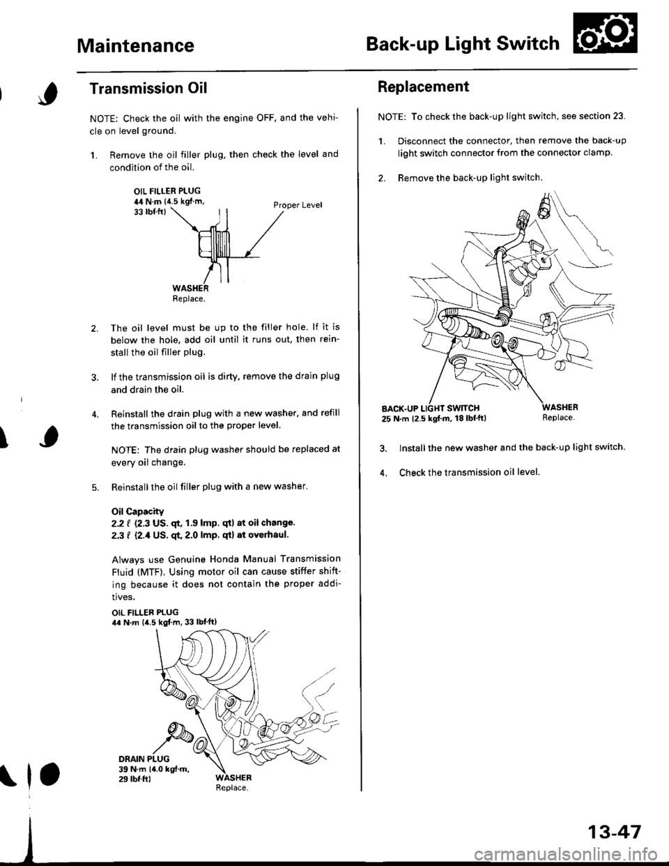
MaintenanceBack-up Light Switch
\
Transmission Oil
NOTE: Check the oil with the engine OFF. and the vehi-
cle on level ground.
1. Remove the oil filler plug, then check the level and
condition of the oil.
OIL FILLER PLUGia4 N.m {{.5 kgf'm,Proper Level33 tbtfrl
The oil level must be up to the filler hole. lf it is
below the hole, add oil until it runs out, then rein-
stall the oil filler plug.
lf the transmission oil is dirty, remove the drain plug
and drain the oil.
Reinstall the drain plug with a new washer. and refill
the transmission oil to the proper level.
NOTE: The drain plug washer should be replaced at
every oil change.
Reinstallthe oilfiller plug with a new washer.
Oil Capacity
2.2 f {2.3 US. qt, 1.9 lmp. qtl at oil change.
2.3 f {2./f US. qt. 2.0 lmp. qt} at overhaul.
Always use Genuine Honda Manual Transmission
Fluid (MTF). Using motor oil can cause stiffer shift-
ing because it does not contain the proper addi-
tives.
OIL FILLER PLUGila N.m {4.5 kgf.m, 33 lbt'ftl
Replace.
\1,
Replacement
NOTE: To check the back-up light switch, see section 23.
1. Disconnect the connector, then remove the back-up
light switch connector from the connector clamp.
2. Remove the back-up lighr switch.
AACK.UP25 N.m 12.5 kgf.m, 18 lbf'tt)Replace.
lnstall the new washer and the back-up light switch.
Check the transmission oil level.4.