Page 1460 of 2189

Compressor (SANDENI
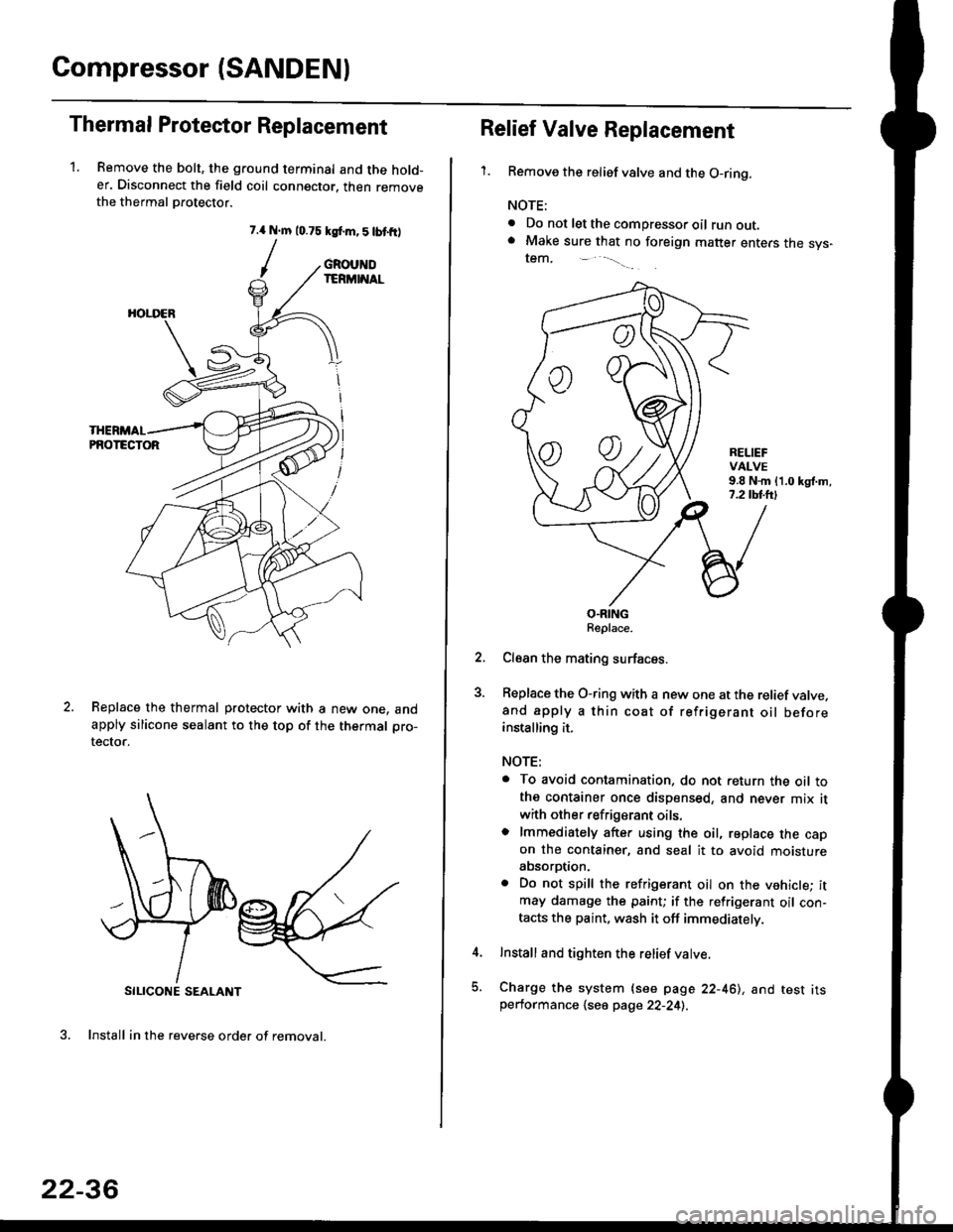
Thermal Protestor Replacement
1. Remove the bolt, the ground terminal and the hold-er. Disconnect the field coil connector. then removethe thermal Drotector.
7.{ N.m 10.75 ksf.m,5lbtfr)
/
SILICONE SEALANT
3. Install in the reverse order of removal.
GROUNDIERMINAL
HOI.I'ER
PNOTECTOR
Replace the thermal protector with a new one. andapply silicone sealant to the top of the thermal pro-
tector.
22-36
oo
Relief Valve Replacement
'1.Remove the relief valve and the O-ring.
NOTE:
. Do not let the compressor oil runout.. Make sure that no foreign matter enters the sys-tem,
RELIEFVALVE9.8 N.m {1.0 kgl.m,7.2 tbl.lrl
O.RINGReplace.
Clean the mating surfaces.
Replace the O-ring with a new one at the relief valve.and apply a thin coat of refrigerant oil beforeinstalling it.
NOTE:
. To avoid contamination. do not return the oil tothe container once dispensed, and never mix it
with other refrigerant oils.o lmmediately after using the oil, replace the capon the container, and seal it to avoid moistureabsorption.
. Do not spill the refrigerant oil on the vehicle; itmay damage the paint; if the refrigerant oil con-tacts the paint, wash it off immediately.
Install and tighten the relief valve.
Charge the system {see page 22-461, and test itsperformance 1se6 page 22-241.
Page 1462 of 2189

Compressor (DENSOI
Replacement (cont'd)
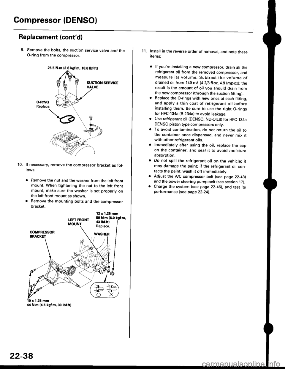
9. Remove the bolts, the suction service valve and theO-ring from the compressor,
lf necessary, remove the compressor bracket as fol-lows.
. Remove the nut and the washer from the left frontmount. When tightening the nut to the left frontmount, make sure the washer is set p.operly onthe left front mount as shown.
a Remove the mounting bolts and the compressor
bracket.
12 x 1,25 rnm59 N.m 16.0 kgfrm,
10.
LEFT FRONTMOUNT€ rbf.fi)Roplace.
WASHEB
x 1.25 mm
2s.5 N.m {2.6 kgf.m. 18.8 tbtttl
4/r N.m {4.5 kgf.m, 33 lbt ft}
22-3A
1 1. Install in the reverse order of removal, and note thesertems:
lf you're installing a new compressor. drain all therefrigerant oil from the removed compressor. andmeasure its volume. Subtract the volume ofdrained oil from '140 ml (4 28 fl{,z, 4.9 lmpoz); theresult is the amount of oil you should drain fromthe new compressor (through the suction fifting).Replace the O-rings with new ones at each fining,and apply a thin coat of refrigerant oil beforeinstalling them. Be sure to use the right O,ringsfor HFC-134a (R-134a) to avoid leakage.
Use refrigerant oil {DENSO, ND-OtL8) for HFC-134aDENSO piston type compressors only.To avoid contamination, do not return the oil tothe container once dispensed, and never mix itwith other refrigerant oils.
lmmediately after using the oil, replace the capon the container, and seal it to avoid moisture
absorption.
Do not spill the refrigerant oil on the vehicle; itmay damage the paint; if the refrigerant oil con-tacts the paint, wash it off immediatelv.
Adjust the ly'C compressor belt (see page 22-43)and the power steering pump belt (see section 17).Charge the system (see page 22-46), and test itsperformance (see page 22-24!..
Page 1664 of 2189
Stereo Sound System
Window Antenna Wire Test
1. Wrap aluminum foil around the tip of the tester
probe as shown.
Touch one tester orobe to the window antenna ter-
minal near, and move the other tester probe along
the antenna wires to check that continuity exists.
WINDOW ANTENNA
23-194
OPEN
Window Antenna Wire Repair
NOTE: To make an effective repair, the broken section
must be no longer than one inch.
1. Lightly rub the area around the broken section with
fine steel wool, then clean it with alcohol.
2. Carefully mask above and below the broken portion
of the window antenna wire with cellophane tape.
CELLOPHANETAPE
Using a small brush, apply a heavy coat of silver
conductive paint extending about 1/8" on both
sides of the break, Allow 30 minutes to dry.
NOTE| Thoroughly mix the paint betore use.
Check for continuity in the repaired wire.
Apply a second coat of paint in the same way. Let it
dry three hours before removing the tape.
Page 1674 of 2189

Rear Window Defogger
Function Test
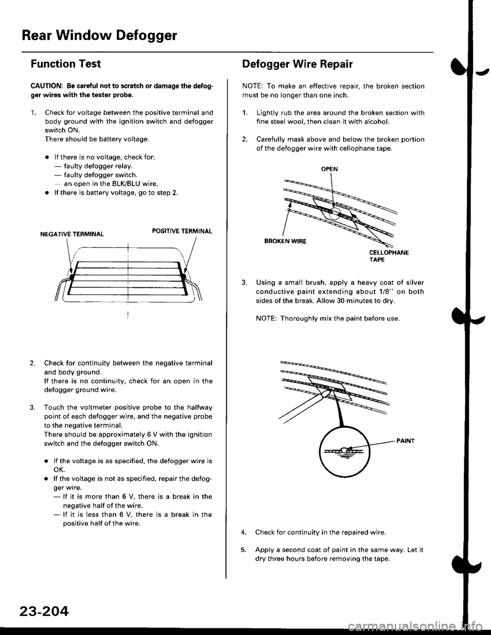
CAUTION: Bs careful nol to scralch or damage the defog-
ger wires with the tester probe,
'1. Check for voltage between the positive terminal and
body ground with the ignition switch and defogger
switch ON.
There should be banery voltage.
. lf there is no voltage, check for:- faulty defogger relay.- faulty defogger switch.
an ooen in the BLK,/BLU wire.
. lf there is battery voltage, go to step 2.
POSITIVE TERMINAL
2. Check for continuity between the negative terminal
and body ground.
lf there is no continuity, check for an open in the
defogger ground wire.
Touch the voltmeter positive probe to the halfway
point of each defogger wire, and the negative probe
to the negative terminal.
There should be approximately 6 V with the ignition
switch and the defogger switch ON.
. lf the voltage is as specified. the defogger wire is
oK.
. lf thevoltage is not as specified, repairthe defog-
ger wrre.- lf it is more than 6 V, there is
negative half of the wire.- lf it is less than 6 V, there is
positive half of the wire.
a break in the
a break in the
23-204
OPEN
?
Defogger Wire Repair
NOTE: To make an effective repair, the broken section
must be no longer than one inch.
1, Lightly rub the area around the broken section with
fine steel wool, then clean it with alcohol.
2. Carefully mask above and below the broken portion
of the defogger wire with cellophane tape.
CELLOPHANETAPE
Using a small brush, apply a heavy coat of silver
conductive paint extending about 1/8" on both
sides of the break. Allow 30 minutes to dry.
NOTE: Thoroughly mix the paint before use.
Check for continuity in the repaired wire.
Apply a second coat of paint in the same way. Let it
dry three hours before removing the tape.
Page 1746 of 2189

Precautions/Procedu res
SRS Unit Precautions
Take extra care when painting or doing body work inthe area below the dashboard. Avoid direct exDosureof the SRS unit or wiring to heat guns, welding. orsprayang equipment.
Disconnect the airbag connector(s) before discon-necting SRS harness connectors (see page24-1|1J.
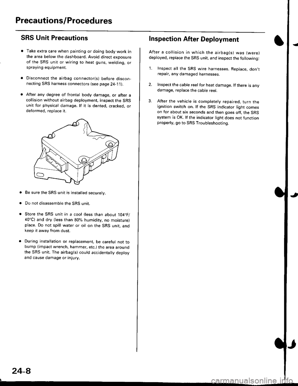
After any degree of frontal body damage, or after acollision without airbag deployment, inspect the SRSunit for physical damage. lf it is dented. cracked, ordeformed, replace it.
Be sure the SRS unit is installed securely.
Do not disassemble the SRS unit.
Store the SRS unit in a cool (less than about 104.F/40"C) and dry (less than 80% humidity, no moisture)place. Do not spill water or oil on the SRS unit, andkeep it away from dust.
During installation or replacement, be careful not tobump (impact wrench, hammer, etc.) the area aroundthe SRS unit. The airbag(s) could accidentally deptoyand cause damage or injury.
24-8
Inspection After Deployment
After a collision ln which the airbag(s) was (were)
deployed, replace the SRS unit, and inspect the following:
1. Inspect all the SRS wire harnesses. Replace. don,trepair, any damaged harnesses.
2. Inspect the cable reel for heat damage. lf there is anydamage, replace the cable reel.
3. After the vehicle is completely repaired, turn theignition switch on. lf the SRS indicator light comeson for about six seconds and then goes off. the SRSsystem is OK. lf the indicator light does not functionproperly, go to SRS Troubleshooting.