1997 HONDA CIVIC IAT sensor
[x] Cancel search: IAT sensorPage 1903 of 2189
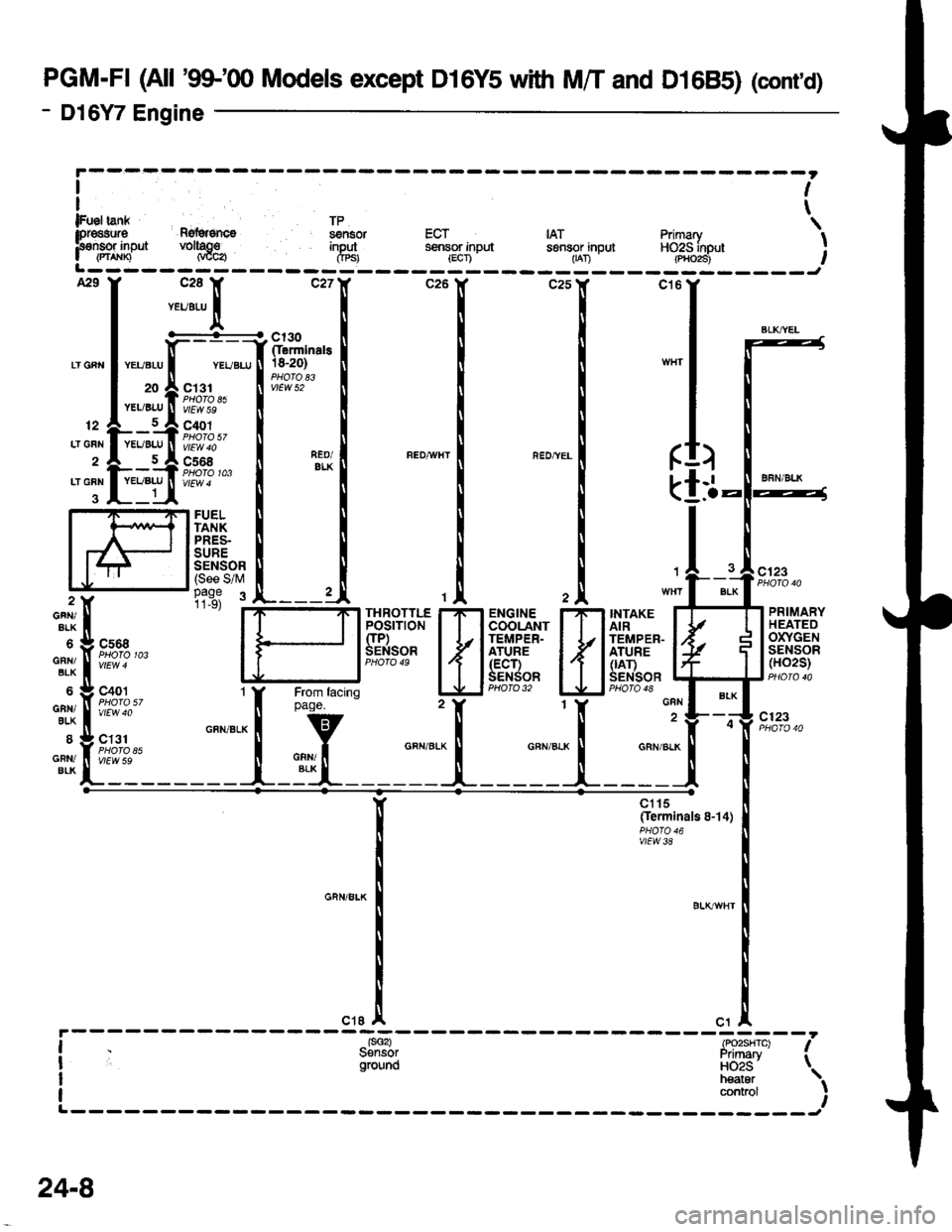
PGM-FI (All '99-'q) Models except D16Y5 with M/T and D1685) (cont'd)
- Dl6Y7 Engine
ct6
(
k
GRN
GRN/ALK
II
)
-l.a
FUELTANKPRES-SURESENSOR(See S/M1
BLK
GFN/BLK
GNN/BLK
6
GAN/8LX
8
GFiI/BIK
tis3 :INTAKEAIRTEMPER-ATURE(|AT)SENSOR
PRIMARYHEATEDOXYGENSENSOR(HO2S)
c'123
c123
cs68PHOTO 103
c401
vtEw 40
ct31
vlEvt S9
FffiflH
{
r,Bi".'#
H
r{
t
f 5:o#'""'"n
rtrt
BLK
at
It
lFueltan* TP \lpr€asura Rg{grsncs ssnsor ECT IAT Primary IF€nsor inpJt voltago input sensor input sensor inpul HO2S inout I| (rt^xn Naca Crpsr lscn - -- 1-ran -- -(p,ioi3i-- ,L------- -----J
BLKT^YEL
clt5(Ierminals 8-14)
vlEw38
contaol
24-8
Page 1980 of 2189
Gauges (cont'd)
- How the Gircuit Works
When the ignition switch is in ON (ll) or START (lll),
battery voltage is supplied through fuse 25 to the
gauges in the gauge assembly.
Speedometer and Odometer
The odometer and soeedometer drive circuits
receive pulses from the vehicle speed sensor
(VSS). The pulse rate increases as the car
accelerates. The frequency and duration of these
input pulses are measured and displayed by the
speedometer, odometer and tripmeter.
Tachometer
The tachometer drive circuit receives pulses from
the ignition control module (lCM) in the distributor
assembly or the ECM/PCM. The solid-state
lachometer then displays these pulses as engine
speed. For each 200 pulses per minute from the
ignition control modul€ (lCM) or the ECM/PCM, the
tachometer displays 100 RPM.
Engine Coolant Temperature Gauge
The engine coolant temperature gauge has two
intersecting coils wound around a permanent
magnet rotor. Voltage applied to the coils, through
fuse 25, generates a magnetic lield. The magnetic
field, controlled by the coolant temperature sending
unit, causes the rotor to rotate and the gauge
needle to move. As the resistance in the sending
unit varies, current through the gauge coils
changes. The gauge needle moves toward the coil
with the strongest magnetic field.
The 6ngine coolant temperature sending unit's
resistance varies from about 137 ohms at low
engine temperature to between 3H6 ohms at high
temperature (radiator fan running).
Refer to the Service Manual (Section 23, Electrical)
for specific tests or troubleshooting procedures.
81-2
(
Fuel Gauge (All except cX)
The fuel gauge has two intersecting coils wound
around a permanent magnet rotor. Voltage applied
to the coils, through tuse 25, generates a magnetic
field. The magnetic field, controlled by the fuel
gauge sending unit, causes the rotor to rotate and
the gauge needle to move. As the resislance in the
sending unit varies, current through the gauge coils
changes. The gauge needle moves toward the coil
with the strongest magnetic field.
The fuel gauge sending unit's resistance varies
from about 2-5 ohms at full, to about 110 ohms at
empty. When you turn the ignition switch off, the
gauge remains at the last reading until you turn the
ignition switch to ON (ll) or START (lll) again,
Refer to the Service Manual (Section 23, Electrical)
for specific tests or troubleshooting procedures.
Fuel Gauge (GX)
The fuel gauge has two intersecting coils wound
around a permanent magnet rotor. Voltage applied
to the coils, through fuse 25, generates a magnetic
field. The magnetic field, controlled by the PCM,
causes the rotor to rotate and the gauge needle to
move. The PCM calculates the gas quantity in the
fuel tank by using the fuel pressure value detected
by the tuel tank pressure sensor and the fuel
temperature value detected by the fuel tank
temperalure sensor, and outputs the signal to the
gauge assembly. The gauge needle moves toward
the coil with the strongest magnetic field.
When you turn the ignition switch off , the gauge
remains at the last reading until you turn the ignition
switch to ON (ll) or START (lll) again. When the
PCM detects a malfunction with the fuel pressure or
temperature, or detects a gas leak, the PCM
reduces the fuel meter to 0.
Refer to the Service Manual GX Supplement
(Section 11 , Fuel and Emissions) for specific tests
or troubleshooting procedures.
a
a
Page 2055 of 2189
How the Circuit Works
Arming the Security System
The security system can be armed:
r By pressing the remote control LOCK button
(if equipped)
. 20 seconds atter closing all doors (C)UDX only)
Arming with the Transmitter
The security system can be armed by removing the
ignition key from the ignition switch, closing all
doors and the trunk, and pressing the LOCK button
on the transmitter. When you arm the system in this
way, the remote control LED comes on, the status
LED flashes once per second, the parking lights
flash once. the doors lock. and the horn sounds
once if the beeo sound mode is on.
Passive Arming (CX and Dx only)
When you turn the ignition to OFF, remove the
ignition key from the ignition switch, and close all
the doors and the trunk; the system will
automatically arm itself 20 seconds after the trunk
or last door is closed. When you arm the system
this way, the status LED tlashes 4 times per second
during the exit delay time, and once per second
after the system is armed; the parking lights will
flash once to confirm that the system is armed.
Triggering the Alarm
Atter you've armed the system, it will trigger the
alarm if any door or the trunldhatch is opened. lf the
battery is disconnected when the system is armed or
in the alarm mode, reconnecting it will immediately
trigger the alarm. When the alarm is triggered, the
following will occur for 30 seconds:
. the horn sounds
o the parking lights flash once per second
. the status LED flashes hvice oer second
. the starter is disabled
After 30 seconds, the alarm will stop and the
system will rearm. Pressing the transmitter
UNLOCK button will disarm the svstem.
tlr
133-13
Disarming the System without the Remote
Transmitter (HX, LX, and EX)
You can disarm the system by turning the ignition
switch to ON (ll) and pressing the disarm/valet
switch on the right side ol the stereo tuner face. The
disarm switch will also disarm the svstem after the
system has been triggered.
Disarming the System with the Remote
Transmitter (Hx, Lx, Ex, DX-V, and Si)
Pressing the transmitter UNLOCK button will disarm
the system. The parking lights llash t\ivice if the
alarm has not been tnggered. The parking lights
flash three times if the alarm has been triggered.
The driver's door will unlock. lf you press the unlock
button twice, it will unlock all doors. lf a door is not
opened within 30 seconds, the system will lock all
doors and rearm.
Disarming the System (CX and DX only)
lf the system arms itself, there is a 20 second delay
after you open a door before the alarm will trigger.
To disarm the system in this mode, simply turn the
ignition switch to the ON position
ldentitying Tripped Sensors
The system identifies which sensor trips the alarm
by flashing the status LED. To display the trip
sensor flash code, press the disarm/valet switch 3
times within 5 seconds after the system has been
disarmed. The status sensor will blink according to
the followino codes:
SensorsNumber of Flashes
Door
TrunldHatch
System Switches
1 blink, pause, repeat
2 blinks, pause, repeat
3 blinks, pause, repeat
For further operating instructions, see the security
syslem owner's manual.
(cont'd)
Page 2143 of 2189
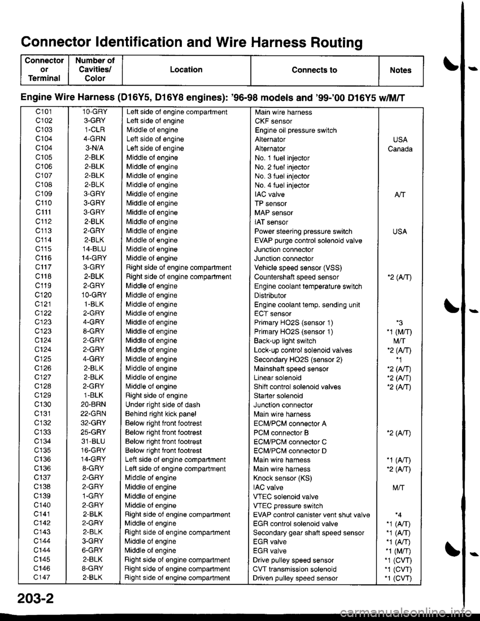
Connector ldentification and Wire Harness Routing
Connector
or
Terminal
Number ot
Cavities/
Golor
LocationConnects toNotes
Engine Wire Harness (Dl6Y5, D16Y8 engines): '96-98 models and '99;00 D16Y5 dM/T
c101
c102
c 103
c104
Q104
c105
c106
c107
cl 08
cl09
cl10
c1l1
cl'12
c113
c114
c'115
c116
c'117
c 118
c119
c120
c121
c122
c123
c123
c124
Q124
c125
c 126
c127
c128
c129
c130
c131
cl32
c 134
c135
c136
c137
c138
c139
c'140
c141
c142
c143
c144
c'|44
c145
c146
c147
1O-GRY
3.GRY
1-CLR
4-GRN
3-N/A
2-BLK
2-BLK
2-BLK
2-BLK
3-GRY
3-GRY
3-GRY
2.BLK
2.GRY
2-BLK
14-BLU
14-GRY
3.GRY
2-BLK
2-GRY
1O-GRY
1.BLK
2.GRY
4-GRY
8-GRY
2-GRY
2.GRY
4-GRY
2.BLK
2.BLK
2-GRY
1.BLK
2O.BRN
22.GRN
32.GRY
25.GRY
31-BLU
16.GRY
14-GRY
8.GRY
2-GFIY
2.GRY
1-GRY
2-GRY
2-BLK
2-GRY
2.BLK
3-GRY
6-GRY
2.BLK
8-GRY
2-BLK
Left side of engine compartment
Left side of engine
Middle of engineI att .i.la ^f an^i^6
Left side ot engine
Middle of engine
Middle of engine
Middle of engine
Middle of engine
Middle of engine
[,liddle of engine
Middle ot engine
Middle ot engine
Middle of engine
Middle of engine
Middle of engine
l\,liddle of engine
Right side of engine compartment
Right side of engine compartment
Middle ot engine
Middle of engine
Middle of engine
Middle of engine
l\,liddle of engine
Nliddle of engine
Middle ot engine
Middle of engine
Middle ot engine
Middle of engine
Middle of engine
Nliddle of engine
Right side of engine
Under right side of dash
Behind right kick panel
Below right front footrest
Below right front footrest
Below right front footrest
Below right front tootrest
Left side ot engine compartment
Left side of engine compartment
Middle of engine
liliddle ot engine
Middle of engine
Nriddle ol engine
Right side of engine compartment
Middle ol engine
Right side of engine compartment
Middle of engine
N,liddle of engine
Right side of engine compartment
Right side of engine compartment
Bight side of engine compartment
Main wire harness
CKF sensor
Engine oil pressure switch
Alternator
Alternator
No. 1 fuel injector
No. 2 fuel injector
No. 3 fuel injector
No.4 fuel injector
IAC valve
TP sensor
MAP sensor
IAT sensor
Power steering pressure switch
EVAP purge control sol€noid valve
Junction connector
Junction connector
Vehicle speed sensor (VSS)
Countershatt speed sensor
Engine coolant temperature switch
Distributor
Engine coolant temp. sending unit
ECT sensor
Primary HO2S (sensor '1)
Primary HO2S (sensor '1)
Back-up light switch
Lock-up control solenoid valves
Secondary HO2S (sensor 2)
lvlainshafl speed sensor
Lanear solenoid
Shift control solenoid valves
Starter solenoid
Junction connector
Main wire harness
ECM/PCM connector A
PCM connector B
ECM/PCNI connector C
ECM/PCl\,,| connector D
Main wire harness
Maln wire harness
Knock sensor (KS)
IAC valve
VTEC solenoid valve
VTEC pressure switch
EVAP control canister vent shut valv€
EGR control solenoid valve
Secondary gear shatt speed sensor
EGR valve
EGR valve
Drive pulley speed sensor
CVT transmission solenoid
Driven pulley speed sensor
USA
Canada
AlT
USA
'2( tr\
'3
-1 (M/r)
t\4/T'2 (Anl'1
'2 (An)'2 (Nr)'2 (AtT)
'2 (Atr)
-1 (An)-2( fi|
M/T
.1 (Arr).1 (A,T)"1 (A/r)-1 (M/r).1 (CVT),1 (cw)'1 (CVT)
203-2
Page 2145 of 2189
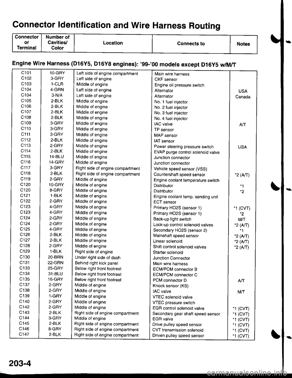
Connector ldentification and Wire Harness Routing
Connector
or
Terminal
Number of
Cavities/
Color
LocationConnects toNotes
Engine wire Harness (Dl6Y5, Dl6Y8 engines): '99-'00 models except D16y5 w/M/T
c 101
c102
c103
cl04
c104
c105
c106
c107
c108
c109
c110
c111
cl12
c1 13
c115
c117
c118
c119
c120
c120
c12'l
cl22
c123
c124
c124
c125
c126
c127
c128
c129
c130
c'131
c133
ct34
c 135
c137
c138
c139
c 140
c142
c143
c144
c'|45
c147
1O-GRY
3.GRY
1-CLR
4-GRN
3-N/A
2.BLK
2.BLK
2-BLK
2.BLK
3-GRY
3-GRY
3.GRY
2-BLK
2.GRY
2-BLK
14-BLU
14-GRY
3-GRY
2-BLK
2-GRY
1O-GRY
8.GRY,1-BLK
2.GRY
4.GRY
4.GRY
2.GRY
2.GRY
4.GRY
2.BLK
2-BLK
2-GRY
1-BLK
2O-BRN
22-GRN
25-GRY
31-BLU
16-GRY
2-GRY
2.GRY
1-GRY
2-GRY
2-GRY
2-BLK
3.GRY
2.BLK
8-GRY
2.BLK
Left side of engine compartment
Left side of engine
Middle of engine
Left side of engine
Left side of engine
Middle ot engine
Middle of engine
N,liddle of engine
l\4iddle of engine
Middle of engine
Niliddle of engine
N,,liddle of engine
Middle of engine
Middle of engine
Middle of engine
Middle of engine
Middle of engine
Rjght side of engine compartment
Right side of engine compartment
Middle of engine
Mlddle of engine
l\4iddle of engine
Middle of engine
Middle of engine
[iliddle of engine
lvliddle of engine
Middle of engine
Middle of engine
l\4iddle of engine
Middle ol engine
Middle of engine
N,liddle of engine
Right side of engine
Under right side of dash
Behind right kick panel
Below right front tootrest
Below right front footrest
Below right lront footrest
[iliddle of engine
l\,liddle of engine
Middle of engine
Middle of engine
L4iddle of engine
Right side of engine compartment
Middle of engine
Right side of engine compartment
Right side of engine compartment
Right side ot engine compartment
Main wire harness
CKF sensor
Engine oil pressure switch
Alternator
Alternator
No. 1 fuel injector
No. 2luel injector
No. 3 fuel injector
No.4 fuel injeclor
IAC valve
TP sensor
MAP sensor
IAT sensor
Power steering pressure switch
EVAP purge control solenoid valve
Junction connector
Junction connector
Vehicle speed sensor (VSS)
Countershaft speed sensor
Engine coolant temperature switch
Distributor
Distributor
Engine coolant temp. sending unit
ECT sensor
Primary HO2S (sensor 1)
Primary HO2S (sensor 1)
Back-up light switch
Lock-up control solenoid valves
Secondary HO2S (sensor 2)
Mainshait speed sensor
Linear solenoid
Shift control solenoid valves
Starter solenoid
Junction Connector
Main wire harness
ECN4/PCM connector B
ECM/PCM connector C
PCM connector D
Knock sensor (KS)
IAC valve
VTEC solenoid valve
VTEC pressure switch
EGR control solenoid valve
Secondary gear shaft speed sensor
EGR valve
Drive pulley speed sensor
CVT transmission solenoid
Driven pulley speed sensor
USA
Canada
ATT
USA
'2 (An\
'1
-1 (cw)
Mft'2 lNr)'1
'2 (Afil'2 (An)'2 (Anl
Atf
t\4/T
-1 (CVr)'1 (CVT).1 (CW)-1 (CVT)'1 (CVT).1 (cw
203-4
Page 2147 of 2189
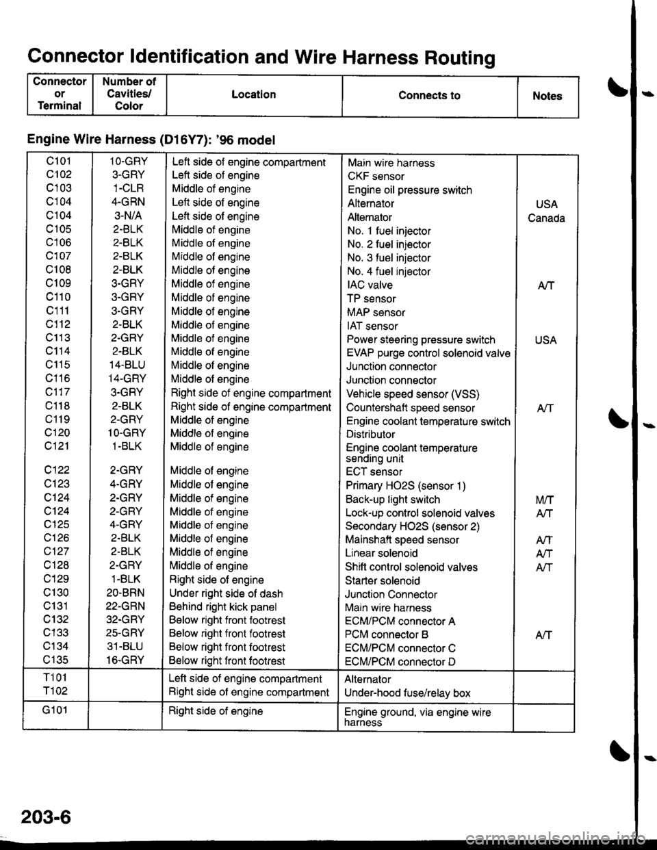
Connector ldentification and Wire Harness Routing
Connector
or
Terminal
Number of
Cavities/
Color
LocationConnects toNotes
Engine Wire Harness (Dl6Y7): '96 model
c101
c102
c103
cl04
c104
c 105
c106
c107
c108
c109
c110
c111
c112
c11 3
c114
c115
c116
c117
c118
c119
c120
c121
c122
c123
c124
cl24
c125
c126
c127
cl28
c129
c130
c131
cl32nl2?
c134al eR
1O.GRY
3-GRY
4.GRN
3-N/A
2.BLK
2-BLK
2-BLK
2-BLK
3.GRY
3-GRY
3.GRY
2-BLK
2.GRY
2-BLK
14-BLU
14-GRY
3.GRY
2.BLK
2-GRY
1O-GRY
1 -BLK
2-GRY
4.GRY
2.GRY
2-GRY
4-GRY
2.BLK
2-BLK
2-GRY
1-BLK
2O-BRN
22-GRN
32.GRY
25-GRY
31-BLU
16.GRY
Left side of engine compartment
Left side of engine
Middle of engine
Left side of engine
Lefl side of engine
Middle of engine
Middle of engine
Middle of engine
Middle of engine
Middle of engine
Middle of engine
Middle of engine
Middle of engine
Middle of engine
Middle of engine
Middle of engine
Middle of engine
Right side of engine compartment
Right side of engine compartment
Middle of engine
Middle of engine
Middle of engine
Middle of engine
Middle of engine
Middle of engine
Middle of engine
Middle of engine
Middle of engine
Middle of engine
Middle of engine
Right side of engine
Under right side of dash
Behind right kick panel
Below right front footrest
Below right front footrest
Below right front footrest
Below right front footrest
Main wire harness
CKF sensor
Engine oil pressure switch
Alternator
Altemator
No. 1 fuel injector
No. 2 fuel injector
No. 3 fuel injector
No. 4 fuel injector
IAC valve
TP sensor
MAP sensor
IAT sensor
Power steering pressure switch
EVAP purge control solenoid valve
Junction connector
Junction connector
Vehicle speed sensor (VSS)
Countershaft speed sensor
Engine coolant temperature switch
Distributor
Engine coolant temperaturesending unit
ECT sensor
Primary HO2S (sensor 1)
Back-up light switch
Lock-up control solenoid valves
Secondary HO2S (sensor 2)
Mainshaft speed sensor
Linear solenoid
Shift control solenoid valves
Starter solenoid
Junction Connector
Main wire harness
ECM/PCM connector A
PCM connector B
ECM/PCM connector C
ECM/PCM connector D
USA
Canada
A/T
USA
Atf
Aff
M/T
Arl
AtT
A/T
Afi
T101
T102
Left side of engine compartment
Right side of engine compartment
Alternator
Under-hood fuse/relay box
G101Right side of englneEngine ground, via engine wirenarness
203-6
Page 2149 of 2189
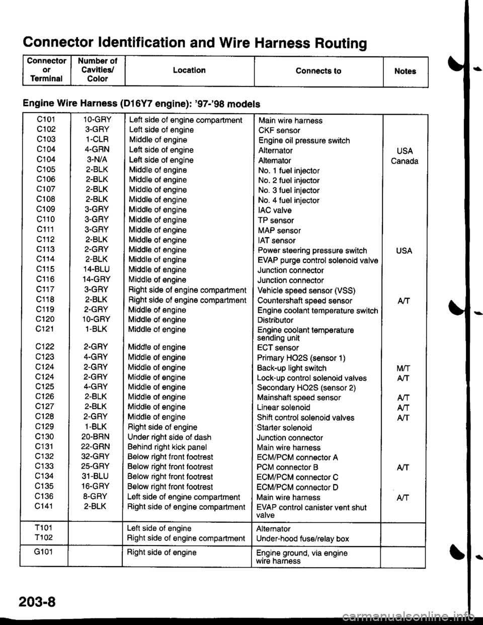
Connector ldentification and Wire Harness Routing
Connector
or
Terminal
Number of
Cavities/
Color
LocationConnects toNoles
Engine Wire Harness (Dl6Y7 engine): '97-'98 models
c101
c102
c103
c104
c104
c105
c106
c107
c108
c109
c110
c111
c113
c114
c115
c116
c118
c119
c'120
c121
c122
c124
c124
c125
c126
c127
c128
c129
cl30
c131
c132
c133
c134
c135
\, | 'tO
c141
1O-GRY
3-GRY
1.CLR
4.GRN
3.N/A
2-BLK
2-BLK
2-BLK
2-BLK
3.GRY
3-GRY
3-GRY
2-BLK
2.GRY
2-BLK
14.BLU
14.GRY
3.GRY
2-BLK
2-GRY
lO.GRY
1-BLK
2-GRY
4.GRY
2.GRY
2-GRY
4.GRY
2.BLK
2.BLK
2-GRY
1-BLK
2O-BRN
22-GRN
32-GRY
25.GRY
31-BLU
16.GRY
8-GRY
2-BLK
Lefl side of engine compartment
Lett side of engine
Middle of engine
Left side of engine
Lefl side of engine
Middle of engine
Middle of engine
Middle of engine
Middle of engine
Middle of engine
Middle of engine
Middle of engine
Middle of engine
Middle of engine
Middle of engine
Middle of engine
Middle of engine
Right side of engine compartment
Right side of ongine compartmont
Middle of engine
Middle of engine
Middle of engine
Middle of engine
Middle of engine
Middle of engine
Middle of engine
Middl€ of engine
Middle of engine
Middle of engine
Middle of engine
Right side of engine
Under right sido of dash
Behind right kick panel
Below right front footrest
Below right front footrest
Below right front footrest
Below right front footrest
Left side of engine compartment
Right side of engine compartmsnt
Main wire hamess
CKF sensor
Engine oil pressure switch
Alternator
Altemator
No. 1 fuel injector
No. 2 fuel iniector
No. 3 fuel iniector
No. 4 fuel injector
IAC valve
TP sensor
MAP sensor
IAT sensor
Power steering pressur€ switch
EVAP purge control solenoid valve
Junction connector
Junction connector
Vehicle speed sensor (VSS)
Countershaft speed sensor
Engine coolant temperature switch
Distributor
Engine coolant temperatu resenorng unI
ECT sensor
Primary HO2S (sensor 1)
Back-up light switch
Lock-up control solenoid valves
Secondary HO2S (sensor 2)
Mainshaft speed sensor
Linear solenoid
Shift conirol solenoid valves
Starter solenoid
Junclion connector
Main wire harness
ECM/PCM connector A
PCM connector B
ECM/PCM connector C
ECM/PCM connsctor D
Main wire harness
EVAP control canister vent shutVAIVE
USA
Canada
USA
Nf
A/T
M/T
A/T
Atl
An
AIT
NT
T101
T102
Left side of engine
Right side of engine compartment
Altemator
Under-hood fuse/relay box
G101Right side of engineEngine ground, via enginewtre narness
203-8
Page 2151 of 2189
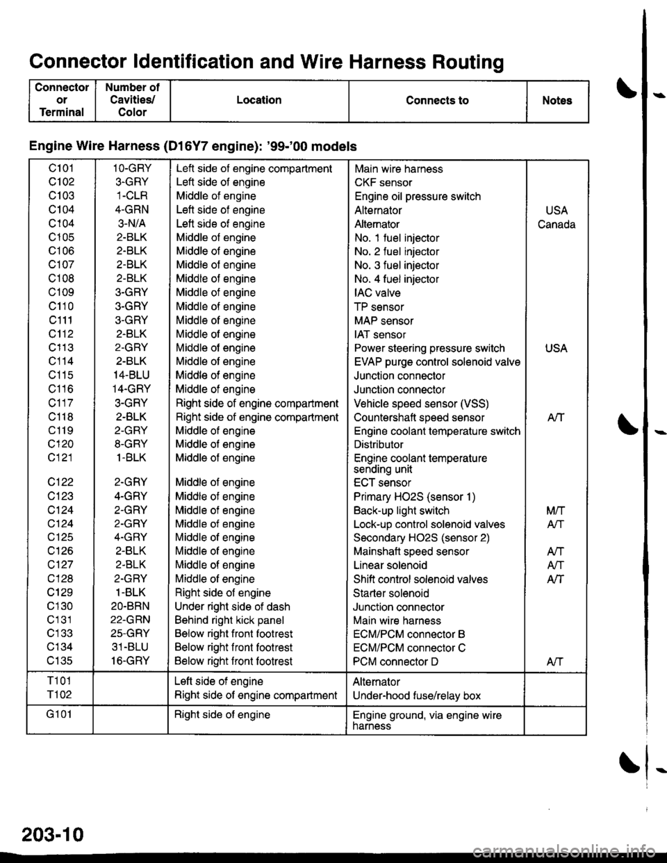
Connector ldentification and Wire Harness Routino
Conneclor
or
Terminal
Number of
Cavities/
Color
LocationConnects toNotes
Engine Wire Harness (Dl6Y7 engine): '99100 models
c101
Q102
c103
c104
c104
c105
UIUO
c107
c108
c109
c110
c111
c112
c113
c114
c11s
c116
c117
c118
c119
c120
c121
c122
c123
c124
cl24
c126
c\27
cl28
cl29
c 130
c131
c'133
c134
v tJc
1O-GRY
3.GRY
1-CLR
4-GRN
3.N/A
2-BLK
2.BTK
2.BLK
2-BLK
3-GRY
3-GRY
3-GRY
2.BLK
2-GRY
2-BLK
14-BLU
14.GRY
3-GRY
2.BLK
2-GRY
8-GRY
1.BLK
2-GRY
4-GRY
2-GRY
2-GRY
4.GRY
2-BLK
2-BLK
2-GRY
1-BLK
2O.BRN
22-GRN
25-GRY
31 -BLU
16-GRY
Left side of engine compartment
Left side of engine
Middle of engine
Left side of engine
Left side of engine
Middle of engine
Middle of engine
Middle of engine
Middle of engine
Middle of engine
Middle of engine
Middle of engine
Middle of engine
Middle ol engine
Middle of engine
Middle of engine
Middle of engine
Right side of engine compartment
Right side of engine compartment
Middle of engine
Middle of engine
Middle of engine
Middle of engine
Middle of engine
Middle of engine
Middle of engine
Middle of engine
Middle of engine
Middle of engine
Middle of engine
Right side of engine
Under right side of dash
Behind right kick panel
Below right front footrest
Below right front footrest
Below right front footrest
Main wire harness
CKF sensor
Engine oil pressure switch
Alternator
Altemator
No. 1 fuel injector
No. 2 fuel injector
No. 3 fuel injector
No. 4 fuel injector
IAC valve
TP sensor
MAP sensor
IAT sensor
Power steering pressure switch
EVAP purge control solenoid valve
Junction connector
Junction connector
Vehicle speed sensor (VSS)
Countershaft speed sensor
Engino coolant temperature switch
Distributor
Engine coolant temperature
sending unit
ECT sensor
Primary HO2S (sensor 1)
Back-up light switch
Lock-up control solenoid valves
Secondary H02S (sensor 2)
Mainshatt speed sensor
Linear solenoid
Shifi control solenoid valves
Starter solenoid
Junction connector
Main wire harness
ECM/PCM connector B
ECM/PCM connector C
PCM connector D
USA
Canada
USA
AIT
Mrl
Atf
AN
A/T
AlT
Afi
T101
r'l02
Left side of engine
Right side of engine compartment
Alternator
Under-hood fuse/relay box
G 101Right side of engineEngine ground, via engine wirenarness
203-10