Page 6 of 192
OVERDRIVE
ON
OFFRES
SET
ACCEL
COAST
Engine coolant
temperature gauge
(pg. 12)
Fuel Gauge
(pg. 12)Speedometer
(pg. 12)Engine oil
pressure gauge
(pg. 13)
Battery
voltage
gauge
(pg. 13)
Warning
lights
(pg. 8)
Speed controls
(pg. 28)
Headlamp switch
and dimmer
(pg. 15)Transmission
control switch
(pg. 24)
Wiper/washer
control
(pg. 27)
Instrumentation
6
Page 9 of 192

in the ON position and the engine
is off.
Transmission control indicator
light (TCIL)
The Transmission Control Indicator
Light (TCIL), which is located on
the gearshift lever, may flash
steadily if a malfunction is
detected. If the TCIL is flashing,
contact your Ford dealer as soon
as possible. If this condition
persists, damage to the
transmission could occur.
The word ªOFFº located on the
end of the gearshift lever is the
transmission control indicator light
(TCIL).
Safety belt
Illuminates when the ignition is
switched on to remind you to
fasten your safety belts. For more
information, refer toUsing the
safety restraints properlyin the
Seating and safety restraints
chapter.
Charging system
Briefly illuminates when the
ignition is turned on and the
engine is off. The light also
illuminates when the battery is not
charging properly, requiring
electrical system service.
Air bag readiness
Briefly illuminates when the
ignition is turned on. If the light
fails to illuminate, continues to
OVERDRIVE OFF
eco_trans_control_light
com_safety_belt.01
com_charging_system.01
com_air_bag.01
Instrumentation
9
Page 35 of 192

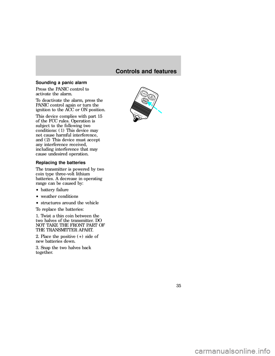
Sounding a panic alarm
Press the PANIC control to
activate the alarm.
To deactivate the alarm, press the
PANIC control again or turn the
ignition to the ACC or ON position.
This device complies with part 15
of the FCC rules. Operation is
subject to the following two
conditions: (1) This device may
not cause harmful interference,
and (2) This device must accept
any interference received,
including interference that may
cause undesired operation.
Replacing the batteries
The transmitter is powered by two
coin type three-volt lithium
batteries. A decrease in operating
range can be caused by:
²battery failure
²weather conditions
²structures around the vehicle
To replace the batteries:
1. Twist a thin coin between the
two halves of the transmitter. DO
NOT TAKE THE FRONT PART OF
THE TRANSMITTER APART.
2. Place the positive (+) side of
new batteries down.
3. Snap the two halves back
together.
LOCK
PANICUN
LOCK
com_remote_batteries.01
com_remote_transmitters.01
Controls and features
35
Page 106 of 192
Number Fuse amperage
ratingCircuits protected
8 30 amp Noise supression
capacitor, ignition coil
positive feed, PCM
relay diode/PCM
power relay, fuel
heater (diesel), glow
plug relay (diesel)
9 30 amp Wiper control module,
wiper motor
10 20 amp Headlamp switch
(exterior lamps),
Multi-function switch
(flash-to-pass)
11 15 amp Stoplight switch, brake
pressure switch,
multi-function switch
12 15 amp Digital transmission
range sensor (backup
lamps), auxiliary
battery relay
13 15 amp A/C mode switch,
blend door actuator
14 5 amp Instrument cluster (air
bag and charge
indicator lamps)
15 5 amp Trailer tow battery
charge relay (coil)
16 30 amp Power seats
17 - Not used
18 - Not used
19 10 amp Air bag module
20 5 amp Overdrive cancel
switch
Roadside emergencies
106
Page 108 of 192
Number Fuse amperage
ratingCircuits protected
43 - Not used
44 - Not used
Power distribution box
Always disconnect the
battery before servicing
high current fuses.
Always replace the cover
to the Power Distribution
Box before reconnecting the
battery or refilling fluid
reservoirs.
Number Fuse amperage
ratingCircuits protected
1 - Generator to battery
2 - Not used
3 - Not used
1A
B
23
4
65
78
9
10
11
12
13
14
1516
17
18
19
20
21
22
23
E
H
J F
G
K24
25
26
27
28
29
C
D
eco_power_dist_box
Roadside emergencies
108
Page 109 of 192
Number Fuse amperage
ratingCircuits protected
4 5 amp PCM keep alive
memory
5 10 amp Right trailer turn
signal
6 10 amp Left trailer turn signal
7 - Not used
8 60 amp Instrument panel
fuses
9 30 amp PCM power relay
10 60 amp Auxiliary battery
11 - Not used
12 60 amp Misc.
13 50 amp Blower motor relay
14 30 amp Trailer running lamps,
trailer backup lamps
15 40 amp Headlamp switch
16 50 amp Auxiliary A/C, remote
keyless entry module
17 30 amp Fuel pump relay
(gasoline), injector
driver module relay
(diesel)
18 60 amp Modified vehicle
power
19 60 amp Anti-lock brake
system (4WABS)
20 20 amp Electric brake
controller (trailer tow)
21 50 amp Modified vehicle
power
22 40 amp Trailer battery charge
(relay)
Roadside emergencies
109
Page 111 of 192
Relays
Relays are located in the power
distribution box
Ford recommends that relays be
replaced by a qualified technician.
Position Circuit
A Not used
B Not used
C Trailer backup lamps
D Trailer running lamps
E Trailer battery charge relay
F Not used
G PCM
H Blower motor
1A
B
23
4
65
78
9
10
11
12
13
14
1516
17
18
19
20
21
22
23
E
H
J F
G
K24
25
26
27
28
29
C
D
eco_relays
Roadside emergencies
111
Page 120 of 192
On vehicles equipped with dual
rear wheels retighten the wheel
lug nuts to the specified torque at
160 km (100 miles), and again at
800 km (500 miles) of new vehicle
operation and at intervals specified
in the ªService Guide.º
On vehicles equipped with single
rear wheels retighten the lug nuts
to the specified torque at 800 km
(500 miles) of operation after any
wheel change or any time the lug
nuts are loosened.
Model Bolt Size Wheel Lug nut Torque*
N²M Ft-Lb
E-150 1/2-20 135 100
E-250, E-350
and E-Super
Duty9/16-18 190 140
* Torque specifications are for nut and bolt threads free of dirt and
rust. Do not use oil or grease on threads. Use only Ford recommened
replacement fasteners.
JUMP STARTING YOUR
VEHICLE
The gases around the
battery can explode if
exposed to flames, sparks, or lit
cigarettes. An explosion could
result in injury or vehicle
damage.
com_jump-starting.01
Roadside emergencies
120