1997 BMW 540i CLUTCH ADJUSTING
[x] Cancel search: CLUTCH ADJUSTINGPage 258 of 1002

Downloaded from www.Manualslib.com manuals search engine
Camshaft Timing Chain
VANOS timing, checking and adjusting
(M52 engine)
NOTE-
* Special BMW service tools are required to remove and in-
stall the VANOS control unit. Read the procedure through
before starting the job.
If the camshafts are not properly timed, the pistons can
contact the valves.
- Disconnect negative (-) cable from battery.
CAUTIOG Disconnecting the battery may erase
faultcode(s) storedin
control module memory. Prior to disconnecting the battery,
checlc for fault codes using special BMW diagnostic equip-
ment.
Prior to disconnecting the battery, read the battery dis-
connection cautions given in
001 General Cautions
and Warnings.
- Remove viscous clutch cooling fan. See 170 Radiator and
Cooling
System.
CAUTIOG The radiator cooling fan nut
(32 mm wrench) has left-hand
threads.
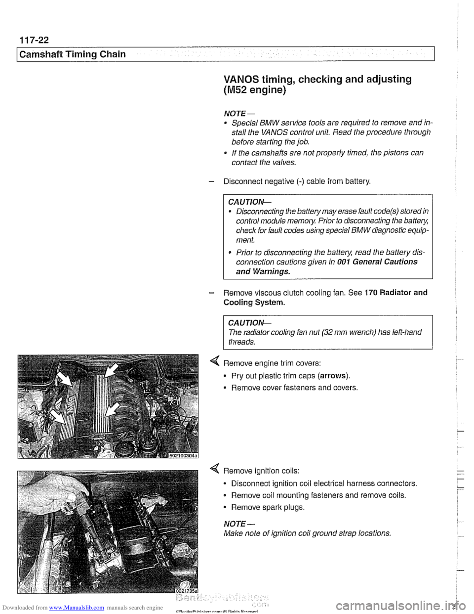
4 Remove ignition coils:
Disconnect ignition coil electrical harness connectors.
Remove coil mounting fasteners and remove coils.
Remove
spark plugs.
NOTE-
Make note of ignition coil ground strap locations.
Page 279 of 1002

Downloaded from www.Manualslib.com manuals search engine
Camshaft Timing Chain
- Connect electrical harness connectors to camshaft position
sensors and VANOS solenoid valves.
- Remove BMW special locking tools from rear of cylinder
head.
- Remove cranltshaft locking tool and replace sealing plug.
Install intake camshaft baffle and cylinder head cover.
Checlc for correct seating of half-moon seals (A) in back of
cylinder head cover.
Use a small amount of Three Bond 1209
O or equivalent
sealant at corners
(B) of half-moon cutouts.
Similarly, seat gasket and
seal corners in front of cylinder
head, at VANOS control unit.
Tightening torque
Cylinder head cover to cylinder head
(M6) 10 Nm (89 in-lb)
- Remainder of installation is reverse of removal.
Tightening torques
Radiator fan (viscous clutch) to
coolant pump 40
Nm (30 ft-lb)
Spark plug to cylinder head
25 Nrn (18 ft-lb)
VANOS timing, checking and adjusting
(M52 TU and M54 engines)
Use this procedure to check and, if necessary, adjust cam-
shaft timing. This procedure assumes that the cylinder head
cover and intake
camshaft plastic baffle have been removed.
Also, be sure the cooling fan and the spark plugs have been
removed.
Remove primary camshaft chain tensioner cylinder
(arrow).
~~ ~ ~~ ~--~
CA UTlOAC
Primary camshaft chain tensioning piston is under spring
pressure.
Page 543 of 1002

Downloaded from www.Manualslib.com manuals search engine
210 Clutch
........................... General .21 0.2
........................ Special tools .21 0.2
Clutch Hydraulics ................. .21 0.4
Clutch hydraulic system.
bleeding and flushing
................. .21 0.4
Clutch master cylinder. replacing
........ .21 0.6
Clutch slave cylinder. replacing ......... .21 0.8 Flywheel. removing
and installing
................... (6 cylinder engine) 210-12
Flywheel. removing and installing
(V-8 engine) ....................... 21 0-1 3
Transmission pilot bearing. replacing .... 210-1 5
Clutch. installing (non-SAC components) . 210-1 6
Clutch. installing (new SAC components)
. 21 0-17
Clutch.
install in^ (used SAC components) 210-19
Clutch Mechanical ................. .21 0.9 self-adjusting crutch (SAC). breaking in : . 210-21
..................... Clutch variations .21 0.9
................... Clutch. removing .21 0.1 1
Clutch components. inspecting
........ .21 0.1 1
Page 544 of 1002

Downloaded from www.Manualslib.com manuals search engine
1 Clutch
This repair group covers replacement of clutch mechanical
and hydraulic components.
BMW 5 Series models with manual transmission use a single
disc hydraulically actuated clutch.
Twoversions of the clutch
are used:
1997
5281 (6 cylinder) uses traditional clutch components.
All 540i (V-8) and 1998 and later
6 cylinder models use a
self-adjusting clutch (SAC).
NOTE-
See 200 Transmission-General for transmission applica-
tion information.
Special tools
Some special tools and techniques are required for clutch re-
pairs. Be sure to read a procedure through before beginning a
job.
< Flywheel loclting tool (V-8 models)
1 (Tool NO. 11 2 070)
-
4 Flywheel loclting tool (6 cylinder models)
(Tool No. 1 1 2 170)
- < Pilot bearino removal tools
11 11 2350 < pilot bearing instaation
(Tool No. 11 2 350) tool
Page 546 of 1002

Downloaded from www.Manualslib.com manuals search engine
Tool for bleeding clutch hydraulics (Tool No. 21 5 030)
21 5 030 I
The clutch is hydraulically actuated by the master and slave
cylinders. With the self-adjusting clutch
(SAC), clutch disc
wear is automatically taken up through the self-adjusting
pressure plate springs, making pedal feel consistent through-
out the life of the clutch.
A soft or spongy feel to the clutch pedal, long pedal free-play,
or grinding noises
from the gears while shifting can all indi-
cate problems with the clutch hydraulics. In these circum-
stances it is best to
star? with a clutch fluid flush, followed, if
necessary, by replacement of the hydraulic parts.
NOTE-
The clutch hydraulic system shares the fluid reservoir and flu-
id with the brake hydraulic system.
Clutch hydraulic system,
bleeding and flushing
If the clutchlbralte fluid is murky or muddy, or has not been
changed within the last two years, flush the system and
change the fluid. Flushing the old fluid from the clutch lines is
done using a bralte system pressure bleeder.
- Remove brake fluid reservoir cap. Using a clean syringe, re-
move brake fluid from reservoir. Refill reservoir with clean
DOT
4 bralte fluid.
Worlting inside engine compartment, remove left
interiorven-
tilation filter housing:
Release 3 plastic taps
(A) on duct. Earlier models use a
single release latch.
Rotate duct inward to remove.
Disconnect electrical harness to hood position switch.
Remove filter housing cover.
Release spring lock
(B) on interior ventilation housing and
remove housing.
Page 551 of 1002

Downloaded from www.Manualslib.com manuals search engine
- Raise and safely support vehicle
WARNING-
Make sure the car is stable and well supporied at all times.
Use a professional automotive /iff orjack stands designed for
the
ournose. A floor jack is not adeouate suooort.
- If necessary, remove transmission splash shield.
- Disconnect fluid line from slave cylinder on lefl side of trans-
mission. Place pan under hose to catch dripping fluid.
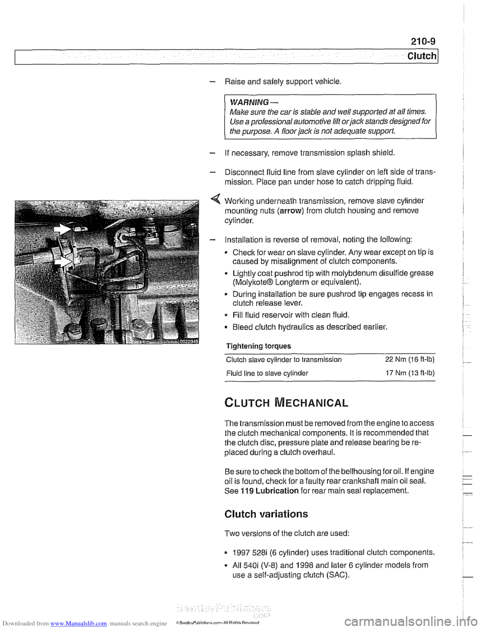
4 Working underneath transmission, remove slave cylinder
mounting nuts (arrow) from clutch housing and remove
cylinder.
- Installation is reverse of removal, noting the following:
Check for wear on slave cylinder. Any wear except on tip is
caused by misalignment of clutch components.
Lightly coat
pushrod tip with molybdenum disulfide grease
(MolyltoteIB Longterm or equivalent).
. During installation be sure pushrod tip engages recess in
clutch release lever.
Fill fluid reservoir with clean fluid.
. Bleed clutch hydraulics as described earlier.
Tightening
toraues - -.
Clutch slave cylinder to transmission 22 Nm (16 R-lb)
Fluid line to slave cylinder 17 Nm (13 ft-lb)
The transmission must be removed from the engine to access
the clutch mechanical components. It is recommended that
the clutch disc, pressure plate and release bearing be re-
placed during a clutch overhaul.
Besure tocheck the bottom of the bellhousing foroil. If engine
oil is found, check for a faulty rear crankshaft main oil seal.
See
119 Lubrication for rear main seal replacement.
Clutch variations
Two versions of the clutch are used:
1997 528i (6 cylinder) uses traditional clutch components.
All
540i (V-8) and 1998 and later 6 cylinder models from
use a self-adjusting clutch (SAC).
Page 552 of 1002

Downloaded from www.Manualslib.com manuals search engine
21 0-1 0
Clutch
Installing the non-SAC clutch (1 997 5281 model) requires the
use of only a flywheel lock and traditional clutch disc align-
ment tool.
Installing the self-adjusting clutch (SAC) requires several
special tools for aligning and assembling the clutch, as well as
locking the flywheel in place. In addition, the procedure for re-
installing a previously used SAC differs from the procedure
for installing
a new SAC. Be sure to read the SAC installation
procedure through before starting the job.
The pressure plate of the SAC uses a spring-loaded wedge
rino to cornoensate for clutch disc wear. The wedge ring
ad-
;u$s by means of spr'ng tenson, so specal toolsh~st be
used to
appy and relieve spring tension as the c utch pres-
sure plate is installed.
Self adjusting clutch (SAC)
and clutch hydraulics
Page 559 of 1002

Downloaded from www.Manualslib.com manuals search engine
Clutch
- Remove flywheel locking tool
4 Inspect and clean release bearing lever. Apply a thin coat of
grease to release bearing lever lubrication points. Install re-
lease bearing. Bearing tabs
(A) align with contact points (B)
on release lever.
CAUTION-
Do not grease release bearing guide sleeve. If guide sleeve
is greased, release bearing may stick to it.
- Clean and lightly lubricate clutch disc splines and transmis-
sion input shaft splines.
- Install transmission. See 230 Manual Transmission
.
Transmission to engine
MB (Torx) 22 Nm (16 fl-lb)
MlO(Torx) 43 Nm (32 fl-lb)
Clutch, installing (new SAC components)
V-8 models and 1998 and later 6 cylinder models are
equipped with the self-adjusting clutch (SAC) pressure plate.
The SAC pressure plate, when new, comes from the factory
with a lock plate at the center which maintains spring tension
on the self-adjusting springs. This
loclting ring must not be re-
moved until the pressure plate is securely installed on tlie fly-
wheel with the clutch disk in place.
CAUTION-
Avoidcontaminating clutch friction surfaces with oilorgrease.
Do not touch these surfaces.
< Center clutch disc on flywheel using centering tool.
5-speed transmission: Special tool 21 2
142
- 6-speed transmission: Special tool 21 2 141
G6S-3782 transmission: Special tool 21 2 201
CAUTION-
Be sure clutch disc is facing the correct way The disc should
be marked "engine side" or "transmission side':
The large bolt in the clutch disc centering tool is used to
in-
stalland remove the tool only. Once the disc is in place on the
eel, remove the bolt to male room for tlie
SACpressure