1997 BMW 540i Battery
[x] Cancel search: BatteryPage 76 of 1002

Downloaded from www.Manualslib.com manuals search engine
11 0-4
/Engine Removal and Installation
- Disconnect negative (-) cable from battery.
CAUTION- Prior to disconnecting the
batteg read the battery discon-
nection cautions
in 001 General Cautions and Warnings.
- Remove engine hood, or place in service position. See 410
Fenders, Engine Hood.
4 Remove left and right interior ventilation ducts (lefl side
shown):
Release ventilation filter cover latch (A) and remove cover.
Release plastic loclting tab
(6) or release locking tabs on
top of duct (later models).
Rotate duct counterclocltwise to
unloclt from bulkhead and
remove (arrow).
Disconnect electrical harness from hood switch (C).
Release spring
loclt (D).
Slide filter housing away from inner fender to remove.
Removal of right side ventilation duct is similar.
Remove rear bulkhead panel:
Remove rubber sealing gasket (arrow).
- Remove 3 mounting clips (A).
Remove
4 retaining screws (6).
Lift off panel.
Remove complete air filter housing:
Loosen
intalte duct hose clamp (A) at throttle assembly.
Loosen clamp and remove idle control line from intalte duct
(6) and (where applicable) disconnect idle speed control
valve electrical harness connector.
Disconnect harness connector (C) from mass air flow sen-
sor.
Remove air filter housing mounting screw (D).
Disconnect vent tube
(E).
Loosen air intake duct clamp (F).
Carefully lift air filter housing out of engine bay.
Page 77 of 1002

Downloaded from www.Manualslib.com manuals search engine
Engine Removal and lnstallationl
< Remove positive battery cable and intake manifold cover:
Remove protective cover from positive (+)jump start post
(4.
Loosen and remove battery lead mounting nut.
Remove lead and push down through intake manifold
Remove trim covers
(arrows) from fuel injector cover.
Remove cover hold down bolts and lift off cover.
Working above engine, disconnect the following:
Vent line from cylinder head cover (A).
M52 engine: Oxygen sensor connectors (8).
Electrical harness connector from intalte camshaft VANOS
solenoid valve
(C).
M52 engine: Disconnect electrical harness connectors at
throttle valve position switch
(D), ASC valve position switch
(E), fuel injector harness (F) and vent valve (G).
CAUTION-
Be sure to mark oxygen sensor harness connectors so that
they can be reassembled correctly Do not interchange con-
nectors.
4 M52 TU, M54 engine: Disconnect fuel injector electrical con-
nectors from injectors.
Use small screwdriverto pry one corner of wire lock clip on
fuel injector
1 connector.
Repeat for all injectors.
Lifl off connector loom and lay aside.
Page 88 of 1002

Downloaded from www.Manualslib.com manuals search engine
110-16
Engine Removal and Installation
ENGINE, REMOVAL AND
INSTALLATION (V-8 MODELS)
NOTE-
Engine removal procedures are similar for all V-8 models.
When differences exist, they are noted at the beginning of
each step. Engine are referred to by engine code. If neces-
sary, See
100 Engine-General for engine code andappli-
cation information.
Be sure to cover all painted surfaces before beginning the
removal procedure. As an aid to installation, label all com-
ponents, wires and hoses before removing them. Do not
reuse gaskets, O-rings or seals during reassembly
WARNING
-
Due to risk ofpersonal injury, be sure the engine is cold be-
fore beginning the
removal procedure.
- Disconnect negative (-) cable from battery.
Prior to disconnecting the battery, read the battery discon-
nection cautions given in
001 General Cautions and
Warnings.
- Remove engine hood or place hood in service position. See
410 Fenders, Engine Hood.
Remove
intake manifold cover, version 1:
Remove plastic trim caps (arrows).
Remove cover mounting fasteners and
lift off cover.
Remove intake manifold cover, version
2:
Press down on locking pins (arrows) to release locks
Lifl cover straight
up to remove.
Page 92 of 1002

Downloaded from www.Manualslib.com manuals search engine
11 0-20
Engine Removal and Installation
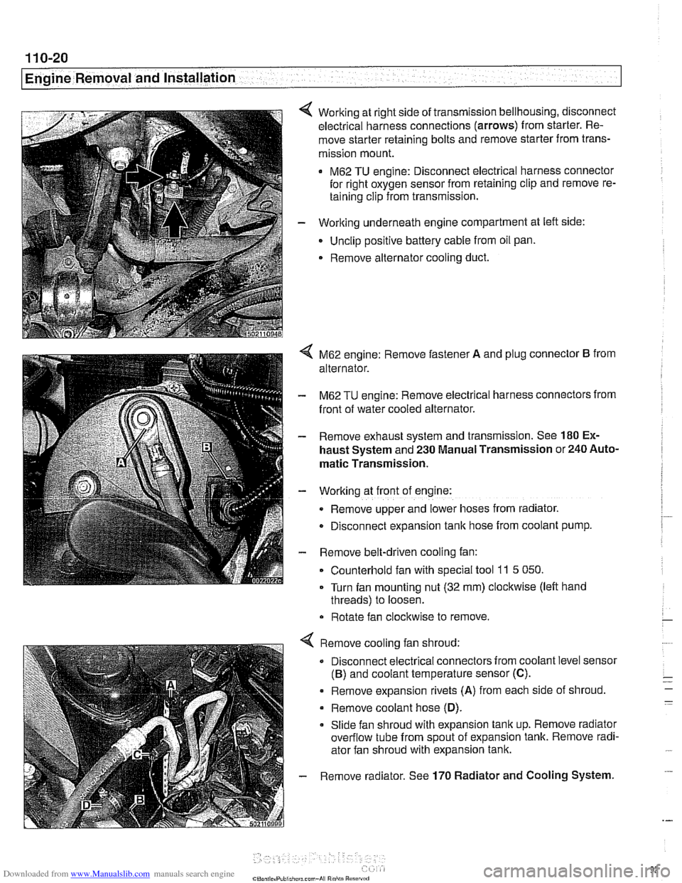
Working at right side of transmission bellhousing, disconnect
electrical harness connections (arrows) from starter. Re-
move starter retaining bolts and remove starter from trans-
mission mount.
M62 TU engine: Disconnect electrical harness connector
for right oxygen sensor from retaining clip and remove re-
taining clip from transmission.
- Working underneath engine compartment at left side:
Unclip positive battery cable from oil pan.
. Remove alternator cooling duct.
4 M62 engine: Remove fastener A and plug connector B from
alternator.
- M62 TU engine: Remove electrical harness connectors from
front of water cooled alternator.
- Remove exhaust system and transmission. See 180 Ex-
haust System and 230 Manual Transmission or 240 Auto-
matic Transmission.
- Working at front of engine:
Remove upper and lower hoses from radiator.
D~sconnect expansion tank hose from coolant pump.
- Remove belt-driven cooling fan:
Counterhold fan with special tool
11 5 050.
Turn fan mounting nut (32 mm) clockwise (left hand
threads) to loosen.
Rotate fan clockwise to remove.
Remove cooling fan shroud:
Disconnect electrical connectors from coolant level sensor
(B) and coolant temperature sensor (C).
. Remove expansion rivets (A) from each side of shroud
Remove coolant hose
(D).
Slide fan shroud with expansion tank up. Remove radiator
overflow tube from spout of expansion tank. Remove radi-
ator fan shroud with expansion tank.
Remove radiator. See
170 Radiator and Cooling System.
Page 99 of 1002

Downloaded from www.Manualslib.com manuals search engine
113-5
Cylinder Head Removal and Installation I
< Fuel line plugs
(Tool No.
BMW 13 5 281113 5 282)
4 Fuel line removal tool for quick-disconnect fittings
(Tool No.
BMW 16 1 050)
< Tensioning bracket (V-8)
(Tool No. BMW 11 7 380)
Compressed air fitting for testing VANOS operation
((Tool No.
BMW 11 3 450)
< Upper timing cover installation tool set, V-8
(Tool No. BMW 11 1 41 0)
Cylinder compression, checking
A compression gauge is needed to make a compression test.
For accurate test, the battery and starter must be capable of
cranking the engine at least
300 rpm, and the engine should
be at normal operating temperature.
NOTE-
Performing a compression test may cause a fault to set in the
ECM and may illuminate the Malfunction
Indicator Light
(MIL). The light can only be turned out using either
BMW
special service scan tools or an equivalent aftermarket scan
tool. Disconnecting the battery will not erase the fault memo-
ry or turn out the light. See OBD On-Board Diagnostics.
Page 102 of 1002

Downloaded from www.Manualslib.com manuals search engine
113-8
[cylinder Head Removal and Installation 1
Cylinder leak-down test
The most conclusive diagnosis of low compression symp-
toms requires a cylinder leak-down test. Using a special
tester and compressed air, each cylinder, in turn, is pressur-
ized. The rate at which the air leaks out of the cylinder, as well
as where the air leaks out, can accurately pinpoint the magni-
tude and location of the leakage.
Before attempting any repair that requires major engine dis-
assembly, use a leak-down test to confirm low compression.
~YL~NDER HEAD REMOVAL AND
~NSTALLATION (M52 ENGINE)
WARNING-
Due to rislc of personal fnjur~: be sure the engine is cold be-
fore beginning the removal procedure.
Cylinder head removal and installation is a time consuming
repair procedure requiring multiple special
service tools.
Read the entire procedure before beginning the repair.
This procedure includes the following steps:
Cylinder head, removing,
M52 engine
Cylinder head, installing,
M52 engine
Cylinder head, removing, M52 engine
- Disconnect negative (-) cable from battery in luggage com-
partment.
CAUTION-
Prior to disconnecting the battea read the battery discon-
nection cautions in 001 General Cautions and Warnings.
-
Page 103 of 1002

Downloaded from www.Manualslib.com manuals search engine
11 3-9
Cylinder Head Removal and Installation
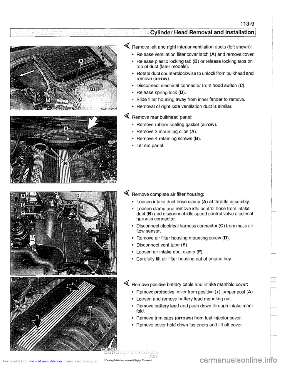
< Remove left and right interior ventilation ducts (left shown):
Release ventilation filter cover latch (A) and remove cover.
Release plastic locking tab
(6) or release locking tabs on
top of duct (later models).
Rotate duct counterclockwise to unlock from bulkhead and
remove (arrow).
Disconnect electrical connector from hood switch
(C).
Release spring lock (D).
Slide filter housing away from inner fender to remove.
Removal of right side ventilation duct is similar.
Remove rear bulkhead panel: Remove rubber sealing
gasket (arrow).
0 Remove 3 mounting clips (A).
Remove
4 retaining screws (6).
Lift out panel.
< Remove complete air filter housing:
Loosen
intake duct hose clamp (A) at throttle assembly.
Loosen clamp and remove idle control hose from
~ntake
duct (6) and disconnect Idle speed control valve electr~cal
harness connector.
Disconnect
electr~cal harness connector (C) from mass alr
flow sensor.
Remove air filter housing mounting screw (D).
Disconnect vent tube
(E).
Loosen air intake duct clamp (F).
Carefully lift air filter housing out of engine bay.
4 Remove positive battery cable and intake manifold cover:
Remove protective cover from positive (+)jumper post (A).
Loosen and remove battery lead mounting nut.
Remove battery lead and push down through intake mani-
fold.
Remove trim caps (arrows) from fuel injector cover.
Remove cover hold down fasteners and lift off cover.
Page 115 of 1002

Downloaded from www.Manualslib.com manuals search engine
- -.
Cylinder Head Removal and lnstallation
NOTE-
Be Sure the secondary timing chain tensioner is locked down
and the exhaust
camshaif mounting bolts are loose before
proceeding.
- Install VANOS control unit. See VANOS control unit, install-
ing
(M52 engine) in 117 Camshaft Timing Chain.
CAUTION--
Incorrect installation ofthe VANOS control may result in dam-
age to the engine valvefrain.
- Install exhaust manifolds using new gaskets and nuts. Coat
manifold studs with copper paste prior to installing nuts.
Install intake camshaft cover and cylinder
head cover.
Check for correct seating of half-moon seals
(A) in back of
cylinder head cover.
Use a small amount of Three Bond 1209
O or equivalent
sealant at corners
(6) of half-moon cutouts.
Seat gasket and seal corners in front of cylinder head at
VANOS unit.
- Installation of remaining parts is reverse of removal, noting
the following:
Reinstall electrical harness connectors for oil pressure
switch and coolant temperature sensor before installing in-
take manifold.
Refill cooling system as described in 170 Radiator and
Cooling System.
Change engine oil and filter as described in 020 Mainte-
nance.
If necessary, adjust accelerator cable.
Reconnect battery last.
Tightening Torques
VANOS oil line
32 Nm (24
ft-lb)
VANOS solenoid to control unit 30 Nm (22 ft-lb)
Coolant drain plug to cylinder
block 25 Nm (18 ft-lb)
Cylinder head cover to cylinder head
10 Nrn (89 in-lb)
(M6 bolts)
intake manifold to cylinder head 15 Nm (I 1 ft-lb)
Radiator cooling fan to coolant pump
40 Nm (30 ft-lb) - . .
Radiator drain screw to radiator 2.5 Nm (22 in-lbl