1997 BMW 540i Battery
[x] Cancel search: BatteryPage 40 of 1002

Downloaded from www.Manualslib.com manuals search engine
--- -
Maintenance
Table b. Inspection I Service (continued)
I I I I
Warm engine Dealer service
required recommended
Check windshield
washer fluid level and
antifreeze protection.
Add washer fluid as necessary.
Replace ventilation
microfilter. (Note:
reduce replacement intervals in dusty
operation conditions)
Reset Service interval Indicator
(Sil).
Additional
repair
information
Tools Required
*
eck aim of washer jets and adjust if
necessary.
covers, obvious damage or attachment o
s or accessories.
Road test
Check braking performance, steering,
heating and air conditioner operation.
Check manual transmission and clutch
operation or automatic transmission
operation. New
parts
required
*
Bodylelectrical
121
630
630
Checic battery state of charge
Check operation of:
headlights,
parking iights, back-up lights.
license plate lights, interior lights,
glove box
illumination, engine compartment light,
trunk light, turn signals, emergency
flashers, stop iights.
Check operation of horn and headlight
dimmer switch
:i:
Page 54 of 1002

Downloaded from www.Manualslib.com manuals search engine
020-22 Maintenance
1
- Installation is reverse of removal, bearing in mind the
following:
Lightly lubricate new
spark plug threads with
copper-based anti-seize compound.
Thread plugs into cylinder head by hand to prevent
cross-threading.
. Be sure to reinstall and tighten coil grounds.
Tightening torque Spark plug
to cylinder head 25 Nm (18 It-lb)
Interior ventilation microfilter, replacing
Two interior ventilation microfilters are used, one on each
side of the engine compartment at the fire wall.
< To replace the microfilter, unclip the wire fastener and
remove the cover.
Lift out the filter, and replace. Left side shown; right is
similar.
Replace cover and clip wire fastener to retain cover.
Battery, checking, cleaning, and replacing
The battery Is located in the right side of the luggage compart-
ment. Simple maintenance of the battery and its terminal
connections will ensure maximum starting periormance,
especially in winter when colder temperatures reduce battery
power.
Battery cables should be tight. The terminals, cable clamps
and battery case should be free of the white deposits that
indicate corrosion and acid salts. Even a thin layer of dust
containing conductive acid salts can cause battery discharge.
Page 55 of 1002

Downloaded from www.Manualslib.com manuals search engine
Maintenance
- To remove battery corrosion:
Disconnect battery cables. Disconnect negative (-)cable
first.
* Remove battery from trunk
Clean terminal posts and cable clamps with a wire brush.
Clean main chassis ground terminal next to battery.
Corrosion can be washed away with a
baking soda and
water solution that will neutralize acid.
Reinstall battery and reconnect cable clamps, positive
(+)
cable first.
Lightly coat outside of terminals, hold down screws, and
clamps with petroleum jelly, grease, or a commercial
battery terminal corrosion inhibitor.
WARNING
-
Battery acid is extremely dangerous. Take care to keep it
from contacting eyes, skin, or clothing. Wear eye protection.
Extinguish all
smolihg materials and do not work near any
oaen flames.
CAUTION-
Prior to disconnecting the batteg read the battery discon-
nection cautions given in
001 General Cautions and
Warnings.
NOTE-
The original equipment battery in E39 models is mainte-
nance free. The original electrolyte will normally last the
entire service life of the battery under moderate climate con-
ditions.
Battery electrolyte should be maintained at the correct level
just above the battery plates and theirseparators. The correct
level is approximately
5 mm ('14 in.) above the top of battery
plates or to the top of the indicator
marks (if applicable). The
battery plates and the indicator marks can be seen once the
fillercaps are removed.
if theelectrolyte level is low, replenish
it by adding distilled water only.
4 The original equipment BMW battery is equipped with a
built-in hydrometer "magic eye"
(arrow). Battery condition is
determined by the color of the eye:
Green: Adequate charge
* Black: Inadequate charge, recharge
Yellow: Defective battery, replace
Batteries are rated by ampere hours (Ah), the number of
hours a specific current drain can be sustained before com-
plete discharge, or by cold cranking amps (CCA), the number
of amps available to crank the engine in cold weather
condi-
Page 56 of 1002

Downloaded from www.Manualslib.com manuals search engine
020-24
Maintenance
tions. In general, replacement batteries should always be
rated equal or higher than the original battery.
The battery is held in place by a single hand screw and plate.
A secure battery hold-down is important in order to prevent
vibrations and road shoclt from damaging the battery.
CAUTION-
Prior to disconnecting the baitem read the battery discon-
nection cautions given in
001 General Cautions and
Warnings.
NOTE-
Always disconnect the negative (-) cable first, and connect
it last. While changing the battery, clean away any corro-
sion in or around the battery tray
More battery and charging system information is in 121
Battery, Alternator, Starter.
Brake fluid, replacing
Brake fluid absorbs moisture easily, and moisture in the fluid
affects bralte performance and reliability. This is why
BMW
strictly recommends replacing the bralte fluid every two
years. When replacing or adding bralte fluid, use only new
fluid from previously unopened containers. Do not use brake
fluid that has been bled from the system, even
if it is brand
new. Use only DOT
4 brake fluid.
NOTE-
See 340 Brakes for brake fluid flushing procedures.
Brake pad 1 rotor wear, checking
Disc brakes are fitted at all four wheels. Although the brakes
are equipped with a brake pad warning system, the system
only monitors one wheel per axle. Pad thickness should be
checked whenever wheels are off or brake
worlt is being
done.
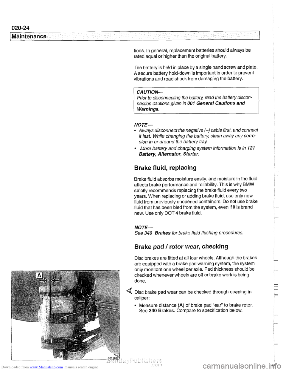
4 Disc brake pad wear can be checked through opening in
caliper:
Measure distance
(A) of brake pad "eai' to bralte rotor.
See
340 Brakes. Compare to specification below.
Page 59 of 1002

Downloaded from www.Manualslib.com manuals search engine
.-. -
Maintenance
Drive axle joint
(CV joint) boots, inspecting
CVjoint protective boots must be closely inspected forcracks
and any other damage that will allow contaminants to get into
the joint.
If the rubber boots fail, the water and dirt that enter
the joint will quickly damage it.
NOTE-
Replacement of the CVjoint boots and inspection of the
joints are described
in 331 Final Drive.
Exhaust system, inspecting
Exhaust system life varies widely according to driving habits
and environmental conditions. If short-distance driving pre-
dominates, the moisture and condensation in the system will
not fully dry out. This will lead to early corrosion damage and
more frequent replacement.
Scheduled maintenance of the exhaust system is limited to
inspection:
* Check to see that all the hangers (arrow) are in place and
properly supporting the system and that the system does
not strike the body.
Check for restrictions due to dents or
kinlts,
Check for weakness or perforation due to rust.
NOTE-
Alignment of the system and the location of the hangers are
described in
180 Exhaust System.
Fuel filter, replacing
The fuel filter is located beneath the center of the car, approx-
imately under the driver's seat.
A protective cover must be
removed to access the filter.
4 Fuel filter for M62 engine (arrow)
- Disconnect battery negative (-) cable
CAUTIOI\C
Disconnecting the battery cables may erase fault codes
stored
in engine control module memory.
WARNING -
Fuel will be expelled forcibly when the filter is removed. Do
notsmoke or work near heaters orother fire hazards. Keep a
fire extinguisher handy
Page 71 of 1002

Downloaded from www.Manualslib.com manuals search engine
Two common causes of driveability problems are incorrect
system voltage and bad grounds.
System voltage
Digital motor electronics (DME) requires that the system (bat-
tery) voltage be maintained within a narrow range of DC volt-
age.
DC voltage levels beyond or below the operating range,
or any
AIC voltage in the electrical system can cause havoc.
When troubleshooting an illuminated MIL, make sure the bat-
tery is fully charged and capable of delivering all its power to
the electrical system. An undercharged battery can amplify
AIC alternator output ripple.
To
make a quick check of the battery charge, measure the
voltage across the battery terminals with all cables attached
and the ignition off.
Afully charged battery will measure 12.6
volts or slightly more, compared to 12.1 5 volts for a battery
with a 25% charge.
The DME system operates at low voltage and current levels,
making it sensitive to small increases in resistance. The elec-
trical system is routinely subjected to corrosion, vibration and
wear, so faults or corrosion in the wiring harness and connec-
tors are not uncommon. Check the battery terminals
forcorro-
sion or loose cable connections. See 121 Battery, Starter,
Alternator for additional information.
If a battery cable connection has no
v~sible faults but is still
suspect, measure the voltage drop across the connection. A
large drop indicates excessive resistance, meaning that the
connection is corroded, dirty, or damaged. Clean or repairthe
connection and retest.
NOTE-
For instructions on conducting a voltage drop test and other
general electrical troubleshooting information, see
600 Elec-
trical System-General.
Visually inspect all wiring, connectors, switches and fuses in
the system. Loose or damaged connectors can cause inter-
mittent problems, especially the small terminals in the ECM
connectors. Disconnect the wiring harness connectors to
check for corrosion, and use electrical cleaning spray to re-
move contaminants.
Main grounds
Good grounds are critical to proper DME operation. If a
ground connection has no visible faults but is still suspect.
measure the voltage drop across the connection. A large volt-
age drop means high resistance. Clean or repair the connec-
tion and retest.
LBuntr.yP~sbhnllcn.can#-AII A,~iltl Rcsrwsd
Page 74 of 1002

Downloaded from www.Manualslib.com manuals search engine
I Engine Removal and Installation
Engine removal and installation are covered in this repail
group.
See 100 Engine-General for engine identification details
and engine codes.
Transmission removal is required for all models before the
engine can be removed. This is best accomplished with the
car raised on an automotive lift. For additional procedures re-
quired during engine removal, refer to the following repair
groups:
020 Maintenance
0 121 Battery, Alternator, Starter
170 Radiator and Cooling System
180 Exhaust System
4 230 Manual Transmission
0 240 Automatic Transmission
410 Fenders, Engine Hood
Special tools
Some special tools are required for engine removal and in-
stallation. Be sure to have the necessary equipment on hand
before starting the job.
Engine lifting tool
(Tool No. BMW
11 0 000)
4 Cooling fan counterhold tool
(Tool No. BMW
11 5 030)
< Cool~ng fan wrench
(Tool No. BMW
11 5 040)
Page 75 of 1002

Downloaded from www.Manualslib.com manuals search engine
110-3
Engine Removal and lnstallationl
Q Fuel line plugs
(Tool No.
BMW 13 5 281 / 13 5 282)
4 Fuel line removal tool
(Tool No.
BMW 16 1 050)
CAUTION-
Disconnecting the battery may erase fault code@) storedin
memoiy Check for fault codes prior to disconnecting the
battery cables.
If the MIL (Malfunction Indicator Light, also may be
called "Check Engine" or "Service Engine Soon" light)
is illuminated, see
OBD On-Board Diagnostics for
DME fault code information.
It orhersysrem faults have been detected, as indicated I
by an ~llum~nated ABS, SRS orASC/DSC ~arning light,
see the appropriate repair group in this manual or an
authorized BMW dealer for more information on fault
codes.
NOTE- Engine removal procedures are similar for all 6-cylinder
models. When differences
exist, they are noted at the be-
ginning of each step. Engine are referred to by engine
code. See
100 Engine-General for engine code and appli-
cation information.
@ Be sure to cover all painted surfaces before beginning the
removal procedure. As an aid to installation, label all com-
ponents, wires and hoses before removing them. Do not
reuse
gaskets, O-rings or seals during reassembly.
The
intake manifold must be removed on &cylinder mod-
els before the engine can be removed.
WARNING-
Due to risk of personal injury, be sure the engine is cold be-
fore beginning the removal procedure.