1997 BMW 328i harness diagram
[x] Cancel search: harness diagramPage 383 of 759

NOTE
-
Sometimes
the
color
of
en
installed
wire
may
be
differ-
ent
than
the
one
on
the
wiring
diagram
.
Don't
be
con-
cerned
.
Just
be
sure
lo
confirm
that
the
wire
connects
lo
the
proper
terminals
.
Wire
color
codes
"
BLU
.........
.
..
..
...
.
.................
Blue
"
BRN
....:....
.
..
..
...
..
...............
Brown
"
YEL
.........
.
..
..
...................
.Yellow
"
GRN
.........
.
..
..
...
.
................
creen
"
G
RY
.......
.
.
.
..
..
.....................
G
ray
"
ORG
.........
.
..
..
...
.
..............
.Orange
"
RED
......
...
.
.
..
.....................
.Red
"
BLK
.........
.
..
..
...
.
................
Black
"
VIO
..........
.
..
...
..
..
.......
.
.......
Violet
"
WHT
.........
.
.
....
.
...
:..............
White
Table
a
.
Terminal
and
Circuit
Numbers
Number
1
Circuít
description
1
j
Low
voltage
switched
terminal
of
coi¡
4
1
High
voltage
center
termina¡
of
coi¡
+x
Originates
atignition
switch
.
Supplies
powerwhen
the
ignition
switch
is
in
the
PARK,
RUN,
or
START
position
15
Originates
atignition
switch
.
Supplies
powerwhen
ignition
switch
is
in
RUN
or
START
position
30
Battery
positive
(+)
voltage
.
Supplies
power
whenever
battery
is
connected
.
(Not
dependent
on
ignition
switch
position,
unfused)
31
1
Ground,
battery
negative
(-)
terminal
50
Supplies
power
from
battery
to
starter
solenoid
when
ignition
switch
isin
START
position
only
+54
Originates
atignition
switch
.
Supplies
power
when
ignition
switch
isin
the
RUN
position
only
85
1
Ground
side
(-)
ofrelay
coil
86
1
Power-in
side
(+)
ofrelay
coil
87
1
Relay
actuatedcontact
D
Alternator
warning
light
and
field
energizing
circuit
ELECTRICAL
SYSTEM-GENERAL
600-
3
Additional
abbreviations
shown
in
the
wiring
diagrams
are
given
below
.
Abbreviations
"
ABS
........
.
...
.
...
.
..........
antilock
brakes
"
A/C
........
.
...
..
..
.
.........
.airconditioning
"
AST/ASC+T
.......
...
.
.
.......
al¡
season
traction
"
CONV
.......
.
.
...
.................
convertible
"
DME
........
.
.
...
.......
digital
motor
electronics
"
ECM
.......
.
...
..
..
.
..
electronic
control
module
"
EWS/EWS
II
......
...
.
.
coded
driveaway
protection
"
SRS
........
.
supplemental
restraint
system-airbag
"
TCM
........
.
..
....
.
transmission
control
module
"
ZKE
(94-98
models)
..
..
.
...
central
body
electronics
"
ZVM
(92-93
models)
...
.
.
..
.
.......
central
locking
ELECTRICAL
TROUBLESHOOTING
Most
terminals
are
identified
by
numbers
on
the
compo-
nents
and
harness
connectors
.
The
terminal
numbers
for
ma-
Four
things
are
required
for
current
toflow
in
any
electrical
jor
electrical
connections
are
shown
in
the
diagrams
.
Though
circuit
:
a
voltagesource,
wires
or
connections
to
transport
the
many
terminal
numbers
appear
only
once,
severa¡other
num-
voltage,
a
load
or
device
that
uses
the
electricity,
and
a
con-
bers
appear
in
numerous
places
throughout
the
electrical
sys-
nection
to
ground
.
Most
problemscanbefound
using
a
digital
tem
and
identify
certain
types
ofcircuits
.
Some
of
the
most
multimeter
(volt/ohm/amp
meter)to
check
for
voltage
supply,
common
circuit
numbers
are
listed
below
in
Table
a
.
for
breaks
in
the
wiring
(infinite
resistance/no
continuity),
orfor
a
path
to
ground
that
completesthe
circuit
.
Electric
current
is
logical
in
its
flow,
always
moving
from
the
voltage
sourcetoward
ground
.
Electricalfaults
can
usually
be
located
through
a
process
of
elimination
.
When
troubleshoot-
ing
a
complex
circuit,
separate
the
circuit
into
smaller
parts
.
The
general
testsoutlined
below
may
be
helpful
in
finding
electrical
problems
.
The
information
is
most
helpful
when
used
with
the
wiring
diagrams
.
Be
sure
to
analyze
the
problem
.
Use
the
wiring
diagrams
to
determine
the
most
likely
cause
.
Getan
understanding
of
how
the
circuit
works
by
following
the
circuit
from
groundback
to
the
power
source
.
When
making
test
connections
at
connectors
andcompo-
nents,
use
care
to
avoidspreading
or
damaging
the
connec-
tors
or
terminals
.
Some
tests
may
require
jumper
wires
to
bypass
components
or
connections
in
the
wiring
harness
.
When
connecting
jumper
wires,
use
bladeconnectors
at
the
wire
ends
that
match
the
size
of
the
terminal
being
tested
.
The
small
interna¡
contacts
are
easily
spread
apart,
and
this
can
cause
intermittent
or
faultyconnections
that
can
leadto
more
problems
.
ELECTRICAL
TROUBLESHOOTING
Page 456 of 759

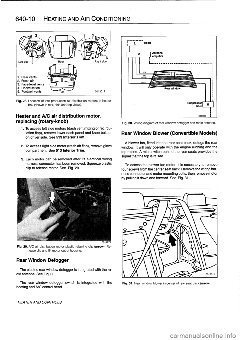
640-10
HEATING
AND
AIR
CONDITIONING
i
El
Radio
Antenna
Rear
.
,
si,-
Left
side
I
d
1
.
Rear
vents
2
.
Fresh
air
3
.
Face-level
vents
4
.
Recirculation
5
.
Footwell
vents
0013017
Fig
.
28
.
Location
oflate
production
air
distribution
motors
in
heater
box(shown
in
rear,
side
and
top
views)
.
Heater
andA/C
air
distribution
motor,
replacing
(rotary-knob)
1
.
Toaccess
left
side
motors
(dash
vent
mixing
or
recircu-
lation
flap),
remove
lower
dash
panel
and
knee
bolster
on
driver
side
.
See
513
Interior
Trim
.
2
.
To
access
right
side
motor
(fresh
air
flap),
remove
glove
compartment
.
See513
Interior
Trim
.
3
.
Each
motor
can
be
removed
after
its
electrical
wiring
harness
connector
has
been
removed
.
Squeeze
plastic
clip
to
release
motor
.
See
Fig
.
29
.
Fig
.
29
.
A/
C
air
distribution
motor
plastic
retaíning
clip
(arrow)
.
Re-
lease
clip
and
tilt
motor
out
of
housing
.
Rear
Window
Defogger
0011877
The
rear
window
defogger
switch
is
integrated
with
the
heating
andA/C
control
head
.
HEATER
AND
CONTROLS
Fig
.
30
.
Wiring
diagram
of
rear
window
defogger
and
radio
antenna
.
Rear
Window
Blower
(Convertible
Models)
A
blower
fan,
fitted
into
the
rear
seatback,
defogs
therear
window
.
It
will
only
operate
with
the
engine
nunning
and
the
top
raised
.
A
microswitch
behindthe
rear
seats
provides
the
signal
that
thetop
is
raised
.
To
access
the
blower
fan
motor,
it
is
necessary
to
remove
four
screwsfrom
the
center
seat
back
.
Remove
the
wiring
har-
ness
connector
and
motor
mounting
boits,
then
remove
motor
by
pulling
it
down
and
forward
.
See
Fig
.
31
.
ri
Suppressor
filter
1
0013005
Fig
.
31
.
Rear
window
blower
in
center
of
rear
seat
back
(arrow)
.
The
electric
rear
window
defogger
is
integrated
with
the
ra-
dio
antenna
.
See
Fig
.
30
.
y
/f
0013014
Page 459 of 759

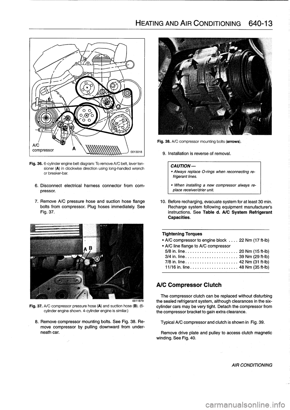
Fig
.
36
.
6-cylinder
engine
belt
diagram
:
To
remove
A/C
belt,
lever
ten-
sioner
(A)
in
clockwise
direction
using
long-handled
wrench
or
breaker-bar
.
6
.
Disconnect
electrical
harness
connector
from
com-
pressor
.
7
.
Remove
A/C
pressure
hose
and
suction
hose
flange
10
.
Before
recharging,
evacuate
system
for
at
least
30
min
.
bolts
from
compressor
.
Plug
hoses
immediately
See
Recharge
system
following
equipment
manufacturer's
Fig
.
37
.
instructions
.
See
Table
d
.
A/C
System
Refrigerant
Capacities
.
0011879
Fig
.
37
.
A/
C
compressor
pressure
hose
(A)
and
suction
hose
(B)
.
(6-
cylinder
engine
shown
.
4-cylinder
engine
is
similar
.)
HEATING
AND
AIR
CONDITIONING
640-
1
3
Fig
.
38
.
A/
C
compressor
mounting
boits
(arrows)
.
9
.
Installation
is
reverseof
removal
.
CAUTION
-
"
Always
replaceO-rings
when
reconnecting
re-
frigerantfines
.
"
When
installlng
a
new
compressor
always
re-
place
receiverldrier
unit
.
Tightening
Torques
"
A/C
compressor
to
engine
block
....
22
Nm
(17
ft-Ib)
"
A/C
line
flange
to
A/C
compressor
5/8
in
.
fine
.
......
.....
....
.
.....
20
Nm
(15
ft-Ib)
3/4
in
.
fine
.......
.....
..........
39
Nm
(29
ft-Ib)
7/8
in
.
fine
...
....
.....
..........
42
Nm
(31
ft-Ib)
11/16
in
.
fine
.....
..
..
..
...
.
.....
48
Nm
(35
ft-Ib)
A/C
Compressor
Clutch
The
compressor
clutch
can
be
replaced
without
disturbing
thesealed
refrigerant
system,
although
clearances
in
the
six-
cylinder
cars
may
be
very
tight
.
Detach
the
compressor
from
the
compressor
bracket
togain
extra
clearance
.
8
.
Remove
compressor
mounting
boits
.
See
Fig
.
38
.
Re-
Typical
A/C
compressor
and
clutch
is
shown
in
Fig
.
39
.
move
compressor
by
pulling
downward
from
under-
neath
car
.
Remove
driveplate
and
pulley
to
access
clutch
magnetic
winding
.
See
Fig
.
40
.
AIR
CONDITIONING
Page 752 of 759

WARNING
Your
common
sense,
good
judge-
ment,
and
general
alertness
are
cru-
cial
to
safe
and
successful
service
work
.
Befcre
attempting
any
work
on
your
BMW,
read
the
warnings
and
cautions
on
page
vi¡
and
the
copyright
page
at
the
frontof
the
manual
.
Review
these
warnings
and
cautions
each
time
you
prepare
to
workon
your
BMW
.
Please
also
read
any
warnings
and
cautions
that
accom-
pany
the
procedures
in
the
manual
.
Door
glass
See
Door
windows
Door
windows
general
information
512-1
front
door
window
(2-door
models)
adjusting
512-7
removing/installing
512-5
front
door
window
(4-door
models)
initíalizing
512-1
removing/installing
512-2
rear
door
window
(4-door
models)
removing/installing
512-4
fixed
glass,
removing/installing
512-
4
rear
vent
window
or
vent
latch,
replacing
(2-door
models)
512-11
window
regulator
and
motor,
removing/installing
512-12
window
regulator
service
512-12Doorcheck
See
DoorsDoor
handle
See
Centrallocking
and
anti-theft
Door
panel
See
Doors
Doors
general
information
411-1
door
adjustment
411-2door
check,
replacing
411-2
door
panels
411-3
doors411-1
front
orrear
door,removing/installing
411-1
front
door
panel,
removing/installing
411-3
rear
door
panel,
removing/installing
411-4
rearsidepanel,
removing/installing
(two-door
model)
411-4
Drive
axle
See
Rear
suspension
Driveability
troubleshooting
See
Engine-general
Driveshaft
general
information
260-1
center
bearing
assembly,
replacing
260-6
driveshaft,
aligning
260-3
driveshaft,
installing
260-4
Driveshaft
(cont
.)
driveshaft,
removing260-4
driveshaftservice
260-3
flex-disc,
replacing
260-5
front
centering
guide,
replacing
260-7
guibo
See
flex-disc
troubleshooting260-1
ECM
(engine
control
module)
pin
assignment
See
Fuel
injection
Electrical
circuit
See
Electrical
system-general
Electrical
component
locations
general
information
610-1
auxíliary
relay
panel
610-2
component
location
table
610-9
component
locations
610-3
fuse
position
tables
610-19
fuse
positions
610-1
relay
positions
610-2
splice
panel,
left
610-2
splice
panel,
right
610-3
Electrical
system-general
general
information
600-1
continuity,
checking
600-5
electrical
test
equipment
600-2
safety
precautions
600-1
short
circuits
600-5
short
circuit,
testing
with
ohmmeter
600-6
short
circuit,
testing
with
voltmeter
600-6
troubleshooting
600-3
voltage,
measuring600-4
voltage
and
polarity
600-1
voltage
and
voltage
drops
600-4
voltage
drop,
testing
600-4
wiring
codes
and
abbreviations
600-2
wiring
diagrams
600-2
wiring,
fuses
and
relays
600-1
Electrical
wiring
diagrams
general
information
ELE-1
wiring
diagrams
ELE-2
ABS
ELE-117
ABS/AST
ELE-120
airbag
(supplemental
restraint
system)
ELE-140
air
conditioning
and
heating
ELE-
129
anti-theft
(Alpine)
system
ELE-144
anti-theft
(EWS
II)
ELE-150
body
computer
module
ELE-176
charging
system
ELE-67
convertible
top
ELE-253
cruise
control
ELE-112
data
link
connector
ELE-86
engine
cooling
ELE-94
engine
management
ELE-70
exterior
lights
ELE-194
ground
distribution
ELE-35
headlights/foglights
ELE-180
INDEX
3
Electrical
wiring
diagrams
(cont
.)
heated
seats
ELE-245
horns
ELE-153
instrument
panel
ELE-165
interior
lights/illumination
ELE-211
lumbar
control
ELE-247
on-board
computer
ELE-173
park
ventilation
ELE-139
power
distribution
ELE-2
power
door
locks
ELE-226
power
mirrors
ELE-241
power
seats
ELE-243
power
sunroof
ELE-248
power
windows
ELE-231
radio/cassette/CD/speakers
ELE-
255
rear
window
defogger
ELE-160
shift
interlock
ELE-110
starting
ELE-63
transmission
electronics
ELE-96
warning
systems`
.
chimes
ELE-178
wiper/washer
ELE-154
Emergencies
See
Fundamentals
for
the
do-it-
yourself
owner
Engine-general
general
information
100-1
air
flow
measurement
and
vacuum
leaks
100-12
basic
engine
settings
100-11
basic
requirements
100-11
battery
voltage
100-12connecting
rods
and
pistons
100-1
cooling
system
100-5
cylinder
block
and
crankshaft100-1
cylinder
compression,
checking
100-6
cylinder
head
and
valvetrain
100-2
DISA
(dual
resonance
intake
system)
100-3,130-3
driveability
troubleshooting
100-8
engine
management
system
100-3
fuel
delivery
100-5
fuel
supply
100-14ground
connections
100-13
ignition
100-5
lubrication
system100-5
mechanical
troubleshooting
100-5
on-board
diagnostics
(OBD)
100-8
oxygen
sensors
100-11
preventive
maintenance
100-11
VANOS
(variable
valve
timing)
100-2warningsand
cautions
100-5
wiring
andharness
connections100-
13Engine
control
module
(ECM)
See
Fuel
injection
Engine
removal
and
installation
general
information
110-1
engine,
removing/installing(4-cylinder
engines)
110-1
engine,
removing/installing
(6-cylinder
engines)
110-4
Engine
coolant
temperature
(ECT)
sensor
See
Fuel
injection
Engine
hood
See
Fenders,
enginehood