Page 3 of 81
24-2
It is possible that the control module will
recognize a malfunction and store a DTC during
some tests. After completing all tests and
repairs, DTC memory should therefore be
checked and erased if necessary. Readiness
code must be generated after DTC memory is
erased Page 01
-73
.
Always switch ignition off before cleaning
engine.
The battery should only be disconnected and
reconnected when the ignition is turned off,
since otherwise the Engine Control Module
(ECM) can be damaged.
WARNING!
Fuel system is under pressure! Before
opening system, place rags around the
connection point. Then release pressure by
carefully loosening connection.
Pa
ge 3 of 81 Motronic fuel in
jection s
ystem, servicin
g
11/21/2002 htt
p://127.0.0.1:8080/audi/servlet/Dis
play?action=Goto&t
yp
e=re
pair&id=AUDI.B5.FU06.24.1
Page 6 of 81
24-5
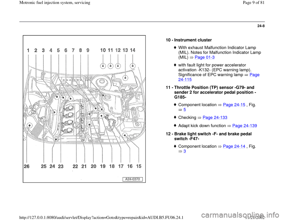
Component locations, overview
Note:
Component location without illustration:
----
- Leak Detection Pump (LDP) -V144-
Behind rear left wheelhousing liner
1 -
Evaporative Emission (EVAP) canister
purge regulator valve -N80- Checking Page 24
-107
2 -
Heated Oxygen Sensor (HO2S) -G39-
before catalytic converter, 55 Nm
Continuous oxygen sensorCheck Oxygen Sensor (O2S) and oxygen
sensor control before Three Way Catalytic
Converter (TWC) Page 24
-71
Check aging of oxygen sensor before
catalytic converter Page 24
-83
Check oxygen sensor heater for Oxygen
Sensor (O2S) before Three Way Catalytic
Converter (TWC) Page 24
-99
Removing and installing Page 24
-105
Pa
ge 6 of 81 Motronic fuel in
jection s
ystem, servicin
g
11/21/2002 htt
p://127.0.0.1:8080/audi/servlet/Dis
play?action=Goto&t
yp
e=re
pair&id=AUDI.B5.FU06.24.1
Page 7 of 81
24-6
Repair Manual, 1.8 Liter 4
-Cyl. 5V Turbo Engine
Mechanical, Engine Code(s): AEB, ATW, Repair Group 26; Secondary Air Injection (AIR) system, checking
3 -
Oxygen Sensor (O2S) behind Three Way
Catalytic Converter (TWC) -G130-, 55 Nm Check Oxygen Sensor (O2S) and oxygen
sensor control behind Three Way Catalytic
Converter (TWC) Page 24
-87
Check oxygen sensor heater for Oxygen
Sensor (O2S) behind Three Way Catalytic
Converter (TWC) Page 24
-99
Removing and installing Page 24
-105
4 -
Combination valve for secondary air
injection (AIR)
Checking, removing and installing:
5 -
Engine Coolant Temperature (ECT) sensor
-G62-
Checking Page 28
-30
Pa
ge 7 of 81 Motronic fuel in
jection s
ystem, servicin
g
11/21/2002 htt
p://127.0.0.1:8080/audi/servlet/Dis
play?action=Goto&t
yp
e=re
pair&id=AUDI.B5.FU06.24.1
Page 8 of 81
24-7
Repair Manual, 1.8 Liter 4
-Cyl. 5V Turbo Engine
Mechanical, Engine Code(s): AEB, ATW, Repair Group 26; Secondary Air Injection (AIR) system, checking
6 -
Fuel pressure regulator Checking Page 24
-33
7 -
Engine Speed (RPM) sensor -G28-
Checking Page 28
-26
8 -
Secondary Air Injection (AIR) solenoid
valve-N112-
Installation position Page 24
-14
, Fig.
4
Checking:Green harness connector
9 -
Bracket for harness connectors Component location Page 24
-13
, Fig.
1
Accessible with coolant expansion tank
unbolted and swung to the side.
Pa
ge 8 of 81 Motronic fuel in
jection s
ystem, servicin
g
11/21/2002 htt
p://127.0.0.1:8080/audi/servlet/Dis
play?action=Goto&t
yp
e=re
pair&id=AUDI.B5.FU06.24.1
Page 9 of 81
24-8
10 -
Instrument cluster
With exhaust Malfunction Indicator Lamp
(MIL). Notes for Malfunction Indicator Lamp
(MIL) Page 01
-3
with fault light for power accelerator
activation -K132- (EPC warning lamp).
Significance of EPC warning lamp Page 24
-115
11 -
Throttle Position (TP) sensor -G79- and
sender 2 for accelerator pedal position -
G185-
Component location Page 24
-15
, Fig.
5
Checking Page 24
-133
Adapt kick down function Page 24
-139
12 -
Brake light switch -F- and brake pedal
switch -F47-
Component location Page 24
-14
, Fig.
3
Pa
ge 9 of 81 Motronic fuel in
jection s
ystem, servicin
g
11/21/2002 htt
p://127.0.0.1:8080/audi/servlet/Dis
play?action=Goto&t
yp
e=re
pair&id=AUDI.B5.FU06.24.1
Page 10 of 81
24-9
Repair Manual, 1.8 Liter 4
-Cyl. 5V Turbo Engine
Mechanical, Engine Code(s): AEB, ATW, Repair Group 26; Secondary Air Injection (AIR) system, checking
13 -
E-box, plenum chamber Installation locations Page 24
-15
, Fig.
6
Installation location for motronic Engine
Control Module (ECM) -J220- with
integrated Barometric pressure (BARO)
sensor -F96- Check voltage supply of Engine Control
Module (ECM) Page 28
-36
Procedure to follow after open circuit in
voltage supply Page 24
-22
Replacing Engine Control Module (ECM)
Page 24
-23
Installation location of Secondary Air
Injection (AIR) pump relay -J299- Check Secondary Air Injection (AIR) pump
relay -J299-:
Pa
ge 10 of 81 Motronic fuel in
jection s
ystem, servicin
g
11/21/2002 htt
p://127.0.0.1:8080/audi/servlet/Dis
play?action=Goto&t
yp
e=re
pair&id=AUDI.B5.FU06.24.1
Page 11 of 81
24-10
Repair Manual, 1.8 Liter 4
-Cyl. 5V Turbo Engine
Mechanical, Engine Code(s): AEB, ATW, Repair Group 21, Charge air system with turbocharger, checking
Installation location of motronic Engine Control
Module (ECM) power supply relay -J271-
Check motronic Engine Control Module (ECM)
power supply relay -J271- Page 28
-13
Installation location of fuse S130 for Secondary
Air Injection (AIR) pump
14 -
Clutch vacuum vent valve switch -F36-
Component location Page 24
-14
, Fig.
3
15 -
Charge air pressure sensor -G31-
Installation position Page 24
-16
, Fig.
7
Checking:
Pa
ge 11 of 81 Motronic fuel in
jection s
ystem, servicin
g
11/21/2002 htt
p://127.0.0.1:8080/audi/servlet/Dis
play?action=Goto&t
yp
e=re
pair&id=AUDI.B5.FU06.24.1
Page 12 of 81
24-11
16 -
Throttle valve control module -J338-
With throttle drive (power accelerator
actuation) -G186-, angle sensor -1- for
throttle drive (power accelerator actuation)
-G187-, and angle sensor -2- for throttle
drive (power accelerator actuation) -G188- Checking Page 24
-120
17 -
Intake Air Temperature (IAT) sensor -G42-
Checking Page 28
-21
18 -
Recirculating valve for turbocharger-
N249-
Installation position Page 24
-14
, Fig.
4
Blue harness connector
19 -
Knock Sensor (KS) 1 -G61-
20 -
Knock Sensor (KS) 2 -G66-
21 -
Camshaft Position (CMP) sensor 2 -G40- Checking Page 28
-45
Pa
ge 12 of 81 Motronic fuel in
jection s
ystem, servicin
g
11/21/2002 htt
p://127.0.0.1:8080/audi/servlet/Dis
play?action=Goto&t
yp
e=re
pair&id=AUDI.B5.FU06.24.1