Page 9 of 33
17-6
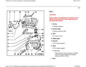
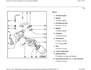
Part II
1 -
Oil filter bracket
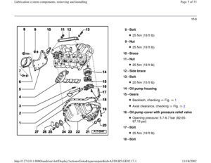
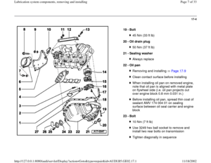
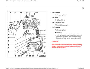
2 -
Gasket Always replace
3 -
Oil retaining valve 8 Nm (71 in. lb)
4 -
Gasket Always replace
5 -
Coupling 30 Nm (22 ft lb)
6 -
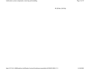
Oil feed line 25 Nm (18 ft lb)To turbocharger
7 -
Bolt 20 Nm (15 ft lb)
8 -
Lower coolant pipe
9 -
Sealing washer If leaking, cut open and replace
10 -
Oil pressure switch -F1-, 1.4 bar (20.3 psi) 25 Nm (18 ft lb)
Pa
ge 9 of 33 Lubrication s
ystem com
ponents, removin
g and installin
g
11/18/2002 htt
p://127.0.0.1:8080/audi/servlet/Dis
play?action=Goto&t
yp
e=re
pair&id=AUDI.B5.GE02.17.1
Page 10 of 33
Black insulationCheck Page 17
-22
Pa
ge 10 of 33 Lubrication s
ystem com
ponents, removin
g and installin
g
11/18/2002 htt
p://127.0.0.1:8080/audi/servlet/Dis
play?action=Goto&t
yp
e=re
pair&id=AUDI.B5.GE02.17.1
Page 11 of 33
17-7
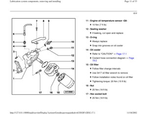
11 -
Engine oil temperature sensor -G8-
10 Nm (7 ft lb)
12 -
Sealing washer If leaking, cut open and replace
13 -
O-ring Always replaceSnap into grooves on oil cooler
14 -
Oil cooler Refer to "CAUTION!" Page 17
-1
Coolant hose connection diagram Page 19
-2
15 -
Oil filter
Follow filter change intervalsUse 3417 oil filter wrench to removeFollow installation notes found on oil filterTightening torque: 20 Nm (15 ft lb)
16 -
Nut 25 Nm (18 ft lb)
17 -
Hex socket bolt 25 Nm (18 ft lb)
Pa
ge 11 of 33 Lubrication s
ystem com
ponents, removin
g and installin
g
11/18/2002 htt
p://127.0.0.1:8080/audi/servlet/Dis
play?action=Goto&t
yp
e=re
pair&id=AUDI.B5.GE02.17.1
Page 12 of 33
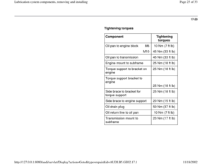
17-8
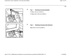
Fig. 1 Checking oil pump backlash
New: 0.05 mm (0.002 in.) Wear limit: 0.20 mm (0.008 in.)
Wear limit: 0.15 mm (0.006 in.) Fig. 2 Checking oil pump axial clearance
Pa
ge 12 of 33 Lubrication s
ystem com
ponents, removin
g and installin
g
11/18/2002 htt
p://127.0.0.1:8080/audi/servlet/Dis
play?action=Goto&t
yp
e=re
pair&id=AUDI.B5.GE02.17.1
Page 13 of 33
17-9
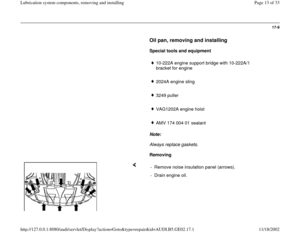
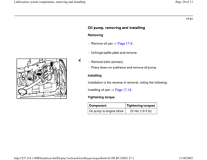
Oil pan, removing and installing
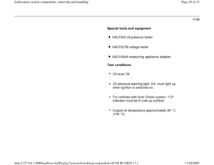
Special tools and equipment
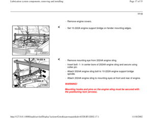
10-222A engine support bridge with 10-222A/1
bracket for engine
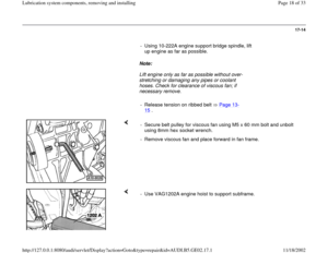
2024A engine sling
3249 puller
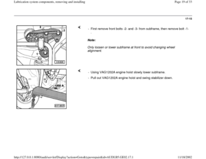
VAG1202A engine hoist
AMV 174 004 01 sealant
Note:
Always replace gaskets.
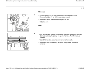
Removing
- Remove noise insulation panel (arrows).
- Drain engine oil.
Pa
ge 13 of 33 Lubrication s
ystem com
ponents, removin
g and installin
g
11/18/2002 htt
p://127.0.0.1:8080/audi/servlet/Dis
play?action=Goto&t
yp
e=re
pair&id=AUDI.B5.GE02.17.1
Page 14 of 33
17-10
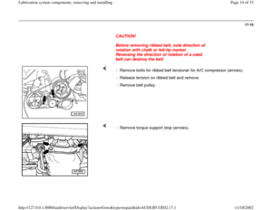
CAUTION!
Before removing ribbed belt, note direction of
rotation with chalk or felt-tip marker.
Reversing the direction of rotation of a used
belt can destroy the belt.
- Remove bolts for ribbed belt tensioner for A/C compressor (arrows).
- Release tension on ribbed belt and remove.
- Remove belt pulley.
- Remove torque support stop (arrows).
Pa
ge 14 of 33 Lubrication s
ystem com
ponents, removin
g and installin
g
11/18/2002 htt
p://127.0.0.1:8080/audi/servlet/Dis
play?action=Goto&t
yp
e=re
pair&id=AUDI.B5.GE02.17.1
Page 15 of 33
17-11
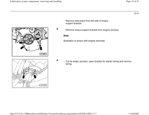
- Remove side brace from left side of torque
support bracket.
Note:
Illustration is shown with engine removed. - Remove torque support bracket from engine (arrows).
- Cut tie wraps (arrows), open bracket for starter wiring and remove
wiring.
Pa
ge 15 of 33 Lubrication s
ystem com
ponents, removin
g and installin
g
11/18/2002 htt
p://127.0.0.1:8080/audi/servlet/Dis
play?action=Goto&t
yp
e=re
pair&id=AUDI.B5.GE02.17.1
Page 16 of 33
17-12
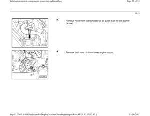
- Remove hose from turbocharger at air guide tube in lock carrier
(arrow).
- Remove both nuts -1- from lower engine mount.
Pa
ge 16 of 33 Lubrication s
ystem com
ponents, removin
g and installin
g
11/18/2002 htt
p://127.0.0.1:8080/audi/servlet/Dis
play?action=Goto&t
yp
e=re
pair&id=AUDI.B5.GE02.17.1

4 -
Gasket Always replace
5 -
Coupling 30 Nm (22 ft lb)
6 -
Oil feed line 25 Nm (18")


12 -
Sealing washer If leaking, cut open and replace
13 -
O-ring Always replaceSnap into grooves on oil cooler
14 -
Oil cooler Re")
 Wear limit: 0.20 mm (0.008 in.)
Wear limit: 0.15 mm (0.006 in.) Fig. 2 Checking oil pump axial clearance
Pa
ge 12 of 33 L")


.
- Cu")
.
- Remove both nuts -1- from lower engine mount.
Pa
ge 16 of 33 Lubrication s
ystem com
ponents, removin")