Page 17 of 75
37-14
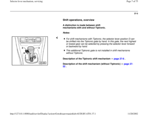
7 -
Compression spring
Removing and installing Page 37
-36
onward
8 -
Pull-lever
Removing and installing Page 37
-36
onward
9 -
Locking clip (thick, with compression
spring)
Secures bushing 17 - in shift mechanism -
4 - Installation position:Angled ends point to
the inner shift mechanism housing
10 -
Stop buffer Clip into cable lever - 12 -Installation position: Large contact surface
to selector lever
11 -
Catch Clip into cable lever - 12 -Removing and installing page 37
-32
Pa
ge 17 of 75 Selector lever mechanism, servicin
g
11/20/2002 htt
p://127.0.0.1:8080/audi/servlet/Dis
play?action=Goto&t
yp
e=re
pair&id=AUDI.B5.AT01.37.1
Page 18 of 75
37-15
12 -
Cable lever
With pivot pin - 18 - secured in shift
mechanism housing - 17 -
13 -
Catch spring with roller For shift positionsRemoving and installing Page 37
-32
onward
14 -
Catch spring with roller
For Tiptronic positionRemoving and installing Page 37
-32
onward
15 -
Frame
Clip or bolt onto shift mechanism housingInstallation position: Ribs toward top
16 -
Nut, 10 Nm
17 -
Shift mechanism housing Removing and installing Page 37
-6
onward
Pa
ge 18 of 75 Selector lever mechanism, servicin
g
11/20/2002 htt
p://127.0.0.1:8080/audi/servlet/Dis
play?action=Goto&t
yp
e=re
pair&id=AUDI.B5.AT01.37.1
Page 19 of 75
37-16
Repair Manual, 5 Spd. Automatic Transmission
01V On Board Diagnostic (OBD), Repair Group 01; Performing On Board Diagnostic (OBD)
18 -
Pivot pin
Secures cable lever - 12 - in shift
mechanism housing - 17 -
19 -
Locking latch For shift lock solenoidRemoving and installing Page 37
-32
onward
20 -
Shift Lock Solenoid -N110-
Removing and installing Page 37
-32
onward
Can be checked via electrical test and read
measuring value block
Pa
ge 19 of 75 Selector lever mechanism, servicin
g
11/20/2002 htt
p://127.0.0.1:8080/audi/servlet/Dis
play?action=Goto&t
yp
e=re
pair&id=AUDI.B5.AT01.37.1
Page 20 of 75
37-17
21 -
Pivot pin
For locking latchRemoving and installing Page 37
-32
onward
22 -
Cover
With seal for shift mechanism housingRemoving and installing Page 37
-6
onward
23 -
Nut, 10 Nm
24 -
Locking clamp
For selector lever cable to cable lever - 12 -Install angled end toward front
25 -
Locking plate For selector lever cable to shift mechanism
housing Install angled end toward the inner shift
mechanism housing
Pa
ge 20 of 75 Selector lever mechanism, servicin
g
11/20/2002 htt
p://127.0.0.1:8080/audi/servlet/Dis
play?action=Goto&t
yp
e=re
pair&id=AUDI.B5.AT01.37.1
Page 21 of 75
37-18
26 -
Selector lever cable
Do not bend or kink, lightly grease coupling
ring and ball socket before installing Removing and installing page 37
-40
Adjusting page 37
-45
In case of damaged rubber boots, the
selector lever cable must be replaced Do not install rubber boot on transmission
side twisted
27 -
Hex bolt, 23 Nm
28 -
Pivot For selector lever cable to transmissionRemoving and installing page 37
-40
Pa
ge 21 of 75 Selector lever mechanism, servicin
g
11/20/2002 htt
p://127.0.0.1:8080/audi/servlet/Dis
play?action=Goto&t
yp
e=re
pair&id=AUDI.B5.AT01.37.1
Page 22 of 75
37-19
29 -
Cable ties
For locking cable
30 -
Ignition/Starter Switch
31 -
Locking cable For ignition key removal lockMust not be kinkedRemoving and installing page 37
-47
Adjusting page 37
-50
32 -
Catch lever
For ignition key removal lockRemoving and installing Page 37
-32
onward
Pa
ge 22 of 75 Selector lever mechanism, servicin
g
11/20/2002 htt
p://127.0.0.1:8080/audi/servlet/Dis
play?action=Goto&t
yp
e=re
pair&id=AUDI.B5.AT01.37.1
Page 23 of 75
37-20
33 -
Retaining spring
For locking cableRemoving and installing Fig. 1
, page
37
-21
34 -
Storing
For selector lever in Tiptronic positionRemoving and installing Page 37
-32
onward
Pa
ge 23 of 75 Selector lever mechanism, servicin
g
11/20/2002 htt
p://127.0.0.1:8080/audi/servlet/Dis
play?action=Goto&t
yp
e=re
pair&id=AUDI.B5.AT01.37.1
Page 24 of 75
37-21
Removing
Installing Fig. 1 Securing spring for locking cable, removing and installing
- To remove locking cable, slightly lift spring at top (arrow B).
- Unhook spring (arrow A) at retaining clip (arrow C) and remove toward
top.
- Insert spring (arrow B) from top and hook in at retaining clip (arrow C).
- Align spring so that it is seated evenly in groove (arrow A).
- To install locking cable, slightly lift spring at top (arrow B).
Pa
ge 24 of 75 Selector lever mechanism, servicin
g
11/20/2002 htt
p://127.0.0.1:8080/audi/servlet/Dis
play?action=Goto&t
yp
e=re
pair&id=AUDI.B5.AT01.37.1


")

, Repair Group 01; Performing On Board Diagnostic (OBD)
18 -
Pivot pin
Secures cable lever - 12 - in shift")


.
- Unhook spring (arrow A) at")