Page 9 of 79
 button: (Only for")
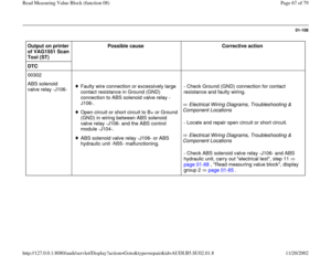
01-67
Test table: display group 3 Read measuring value block
3
Indicated on display
60 to
8000
1 RPM 0 to
100
%
0 or 1
---
Traction control (ASR) button: (Only for vehicles equipped with ASR)
0 Traction control button not operated. 1 The traction control button is operated, operational condition of ASR alternates, i.e. "ASR
OFF" and "ASR ON". When ASR is switched off via the traction control button, the warning lamp for ASR lights up.
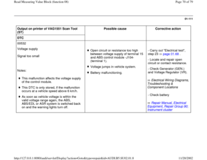
- Check traction control button if there are deviations. Carry out "Electrical test", step 22 page 01
-
68
.
Actual engine torque (AET): (Only for vehicles equipped with ASR)
0% vehicle is in deceleration mode.20% - 30% represents engine idle.100% engine is offering its maximum torque.
- If no indication is displayed, proceed according to DTC 00647 "ABS-ASR engine electrical connection 2". DTC
table page 01
-98
.
Engine speed: (Only for vehicles equipped with ASR)
Engine speed is displayed in increments of 60 RPM, starting at 60 RPM.
Pa
ge 9 of 79 Read Measurin
g Value Block
(function 08
)
11/20/2002 htt
p://127.0.0.1:8080/audi/servlet/Dis
play?action=Goto&t
yp
e=re
pair&id=AUDI.B5.SU02.01.8
Page 10 of 79
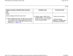
- If no indication is displayed, proceed according to DTC 00529 "Wheel speed information missing. No signal". DTC table
page 01
-98
.
Pa
ge 10 of 79 Read Measurin
g Value Block
(function 08
)
11/20/2002 htt
p://127.0.0.1:8080/audi/servlet/Dis
play?action=Goto&t
yp
e=re
pair&id=AUDI.B5.SU02.01.8
Page 11 of 79
01-68
Electrical testing
If the On Board Diagnostic (OBD) sequence
does not provide any indication of the source of
the malfunction, work through all of the
electrical test steps.
If the OBD sequence identifies the source of the
malfunction, only carry out the test steps
recommended in the DTC table (specific
testing).
Test requirements
The "Automatic Test Sequence" was carried
out and it was determined that the
Transmission Control Module (TCM) and
Engine Control Module (ECM) only contain
DTCs relating to ABS.
- Connect the VAG1551 Scan Tool (ST) and
select the address word 00 with ignition
switched on;
- After completing electrical test, check and
erase DTC memories of Transmission Control
Module (TCM) and Engine Control Module
(ECM).
Pa
ge 11 of 79 Read Measurin
g Value Block
(function 08
)
11/20/2002 htt
p://127.0.0.1:8080/audi/servlet/Dis
play?action=Goto&t
yp
e=re
pair&id=AUDI.B5.SU02.01.8
Page 12 of 79
01-69
Note:
The operation manual for the VAS1978 wiring harness repair kit generally
forbids the repair of any lines in the ABS or related systems. This rule only
pertains to the shielded lines in these systems.
Multi-pin harness connector for ABS control module -J104- in proper
condition, with no bent, broken or corroded terminals. Replace any
damaged terminals using VAS1978 wiring repair kit. Ignition and electrical consumers switched off before beginning
testing (headlights, lighting, fan, etc.). For steps 13 through 16, raise the vehicle until the wheels rotate
freely. On vehicles with manual transmission put the gear shift lever in
neutral. On vehicles with automatic transmission move the selector
lever to position "N".
Pa
ge 12 of 79 Read Measurin
g Value Block
(function 08
)
11/20/2002 htt
p://127.0.0.1:8080/audi/servlet/Dis
play?action=Goto&t
yp
e=re
pair&id=AUDI.B5.SU02.01.8
Page 13 of 79
01-70
Required special tools and test equipment:
VAG1598/20 test box
VAG1594 connector test kit
VAG1526 Multimeter
VAG1310A Pressure gauge
Pa
ge 13 of 79 Read Measurin
g Value Block
(function 08
)
11/20/2002 htt
p://127.0.0.1:8080/audi/servlet/Dis
play?action=Goto&t
yp
e=re
pair&id=AUDI.B5.SU02.01.8
Page 14 of 79
01-71
Connecting the VAG1598/20 test box and
checking the ABS, ABS/EDL or ASR system
- Switch ignition off.
- Remove ABS control module -J104-.
Repair manual, Brake System, Repair Group
45
- Disconnect multi-pin connector from ABS control
module -J104-.
- Check multi-pin connector between harness
connector and ABS control module -J104-.
The socket designations on the VAG1598/20 test box are identical to the
terminal designations on the ABS control module -J104- and on the wiring
harness connector.
Electrical Wiring Diagrams, Troubleshooting & Component Locations - Connect VAG1598/20 test box to multi-pin connector of ABS wiring
harness.
Pa
ge 14 of 79 Read Measurin
g Value Block
(function 08
)
11/20/2002 htt
p://127.0.0.1:8080/audi/servlet/Dis
play?action=Goto&t
yp
e=re
pair&id=AUDI.B5.SU02.01.8
Page 15 of 79
 -J104- Terminal
Wire connection to component ...
1
Voltage supply, terminal 15 2
Hydraulic u")
01-72
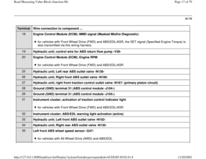
Terminal assignment of multi-pin connector for wiring harness / ABS control module (w/EDL) -J104- Terminal
Wire connection to component ...
1
Voltage supply, terminal 15 2
Hydraulic unit; activation of ABS return flow pump relay -J105- 3
Hydraulic unit; left front traction control switch-over valve -N168- (secondary piston circuit) 4
Hydraulic unit; left front traction control outlet valve -N169- (secondary piston circuit) 5
Hydraulic unit; left front ABS inlet valve -N101- 6
Hydraulic unit; right rear ABS inlet valve -N133- 7
Hydraulic unit; activation of ABS return flow pump relay -J105- 9
Left front ABS wheel speed sensor -G47-
for vehicles with Front Wheel Drive (FWD) and ABS/EDLfor vehicles with Front Wheel Drive (FWD) and ABS/EDL/ASR
10
Left front ABS wheel speed sensor -G47- 11
Right rear ABS wheel speed sensor -G44- 12
Left rear ABS wheel speed sensor -G46- 13
Left rear ABS wheel speed sensor -G46- 14
Right front ABS wheel speed sensor -G45- 15
Right front ABS wheel speed sensor -G45-
for vehicles with Front Wheel Drive (FWD) and ABS
Pa
ge 15 of 79 Read Measurin
g Value Block
(function 08
)
11/20/2002 htt
p://127.0.0.1:8080/audi/servlet/Dis
play?action=Goto&t
yp
e=re
pair&id=AUDI.B5.SU02.01.8
Page 16 of 79
for vehicles with Front Wheel Drive (FWD) and ABS/EDLfor vehicles with Front Wheel Drive (FWD) and ABS/EDL (ABS pressure regulation)
Pa
ge 16 of 79 Read Measurin
g Value Block
(function 08
)
11/20/2002 htt
p://127.0.0.1:8080/audi/servlet/Dis
play?action=Goto&t
yp
e=re
pair&id=AUDI.B5.SU02.01.8


11/2")
 sequence
does not provide any indication of the source of
the malfunction, work through all of the
electrical test steps.")


 and ABS/EDLfor vehicles with Front Wheel Drive (FWD) and ABS/EDL (ABS pressure regulation)
Pa
ge 16 of 79 Read Measurin
g Value Block
(function 08
)
11/20/20")