Page 17 of 65
01-316
Multi-pin connector at ABS control module
(w/EDL) -J104- Terminal
Connected to...
Terminal
81
Not assigned
-
82
Not assigned
-
83
Not assigned
-
84
Not assigned
-
85
Not assigned
-
86
not occupied; (control module 4B0 907 389)
-
86
Instrument cluster; standing time signal; (control module
8D0 907 389/A/D/E)
11
87
Not assigned
-
88
Not assigned
-
Electrical Wiring Diagrams, Troubleshooting & Component Locations
Pa
ge 17 of 65 Electronic Stabilization Pro
gram
(ESP
), electrical testin
g
11/20/2002 htt
p://127.0.0.1:8080/audi/servlet/Dis
play?action=Goto&t
yp
e=re
pair&id=AUDI.B5.SU02.01.16
Page 18 of 65
 -J104- in the wiring diagram. Incorrect")
01-317
Notes:
For test table
The socket designations of the VAG1598 test box are identical to the terminal designations of the ABS control module
(w/EDL) -J104- in the wiring diagram. Incorrect test procedures can cause damage to the system. Do not bridge any
terminals other than those listed in the table.
Electrical Wiring Diagrams, Troubleshooting & Component Locations Specified values refer to readings on the VAG1526 and are not necessarily applicable for other test units.
If the measured values do not match specifications, carry out the corrective actions listed on the right side of the table.
Electrical Wiring Diagrams, Troubleshooting & Component Locations If values are obtained, also check wiring for intermittent loose terminals and short circuit to B+ and Ground (GND). This
applies especially to sporadic malfunctions.
Use the VAG1594 connector test kit for checking continuity (bridges).
If the measured values only differ slightly from the specifications, clean the sockets and harness connectors of the testers
and adapter leads (using contact spray G 000 700 04) and repeat the test. Before replacing actual components, check
wiring and connections once more. This is especially important if the specification for a resistance test is under 10 .
Pa
ge 18 of 65 Electronic Stabilization Pro
gram
(ESP
), electrical testin
g
11/20/2002 htt
p://127.0.0.1:8080/audi/servlet/Dis
play?action=Goto&t
yp
e=re
pair&id=AUDI.B5.SU02.01.16
Page 19 of 65
01-318
Electrical test; steps 1-12
Resistance measurement: Select measurement range on VAG1526 (200 ) Test
step VAG
1598/20
sockets Test of
Test
requirements
- Additional work
steps Specified
value Corrective action
1 5 + 3 Left front ABS inlet valve
-N101-, left front ABS
outlet valve -N102-
- An infinitely high resistance indicates
an open circuit. Check for this.
2 55 + 26 Right front ABS inlet
valve -N99-, right front
ABS outlet valve -N100-
9 22
- A resistance less than the specified
value indicates a short circuit between
both lines. Check for this.
3 53 + 25 Inlet valve -N134-, outlet
valve -N136- left-rear
- Check electrical wiring for short
circuit to Ground (GND) or B+.
Pa
ge 19 of 65 Electronic Stabilization Pro
gram
(ESP
), electrical testin
g
11/20/2002 htt
p://127.0.0.1:8080/audi/servlet/Dis
play?action=Goto&t
yp
e=re
pair&id=AUDI.B5.SU02.01.16
Page 20 of 65
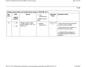
01-319
Resistance measurement: Select measurement range on VAG1526 (200 ) Test
step VAG
1598/20
sockets Test of
Test
requirements
- Additional work
steps Specified
value Corrective action
4 6 + 4 Inlet valve -N133-,
outlet valve -N135-
right-rear
9 22
Electrical Wiring Diagrams,
Troubleshooting & Component Locations - If the electrical wiring is OK, replace the
hydraulic unit.
5 49 + 50
Pilot valve -1-
traction control -
N225-
- An infinitely high resistance indicates an
open circuit. Check for this.
Pilot valve -2-
traction control -
N226-
12
28
- A resistance less than the specified
value indicates a short circuit between
both lines. Check for this.
Pa
ge 20 of 65 Electronic Stabilization Pro
gram
(ESP
), electrical testin
g
11/20/2002 htt
p://127.0.0.1:8080/audi/servlet/Dis
play?action=Goto&t
yp
e=re
pair&id=AUDI.B5.SU02.01.16
Page 21 of 65
01-320
Resistance measurement: Select measurement range on VAG1526 (200 ) Test
step VAG
1598/20
sockets Test of
Test
requirements
- Additional work
steps Specified
value Corrective action
6 52 + 54
High pressure switch
valve -1- traction control
-N227-
W
16
- Check electrical wiring for short
circuit to Ground (GND) or B+.
High pressure switch
valve -2- traction control
-N228- Electrical Wiring Diagrams,
Troubleshooting & Component
Locations
- If the electrical wiring is OK,
replace the hydraulic unit.
7
8 + 10
1)
9 + 10 2) Left front ABS wheel speed
sensor -G47-
400
2300
- An infinitely high resistance
indicates an open circuit. Check for
this.
Outlets on ABS control module -J104- differ depending on installed equipment
1) Vehicles with all-wheel-drive
Pa
ge 21 of 65 Electronic Stabilization Pro
gram
(ESP
), electrical testin
g
11/20/2002 htt
p://127.0.0.1:8080/audi/servlet/Dis
play?action=Goto&t
yp
e=re
pair&id=AUDI.B5.SU02.01.16
Page 22 of 65
2) Vehicles with front-wheel-drive
Pa
ge 22 of 65 Electronic Stabilization Pro
gram
(ESP
), electrical testin
g
11/20/2002 htt
p://127.0.0.1:8080/audi/servlet/Dis
play?action=Goto&t
yp
e=re
pair&id=AUDI.B5.SU02.01.16
Page 23 of 65
01-321
Resistance measurement: Select measurement range on VAG1526 (2k or 20 k )
Test
step VAG
1598/20
sockets Test of
Test
requirements
- Additional work
steps Specified
value Corrective action
8 15 + 16 Right front ABS
wheel speed
sensor -G45-
- A resistance less than the specified value
indicates a short circuit between both lines.
Check for this.
9 13 + 14 Left rear ABS
wheel speed
sensor -G46-
400
2300
- Check electrical wiring for short circuit to
Ground (GND) or B+.
10 11 + 12 Right rear ABS
wheel speed
sensor -G44- Electrical Wiring Diagrams,
Troubleshooting & Component Locations - If the electrical wiring is OK, replace the
relevant ABS wheel speed sensor.
Pa
ge 23 of 65 Electronic Stabilization Pro
gram
(ESP
), electrical testin
g
11/20/2002 htt
p://127.0.0.1:8080/audi/servlet/Dis
play?action=Goto&t
yp
e=re
pair&id=AUDI.B5.SU02.01.16
Page 24 of 65
 Test
step VAG
1598/20
sockets Test of
Test
requirements
- Additional work
steps Specified
value Corrective ac")
01-322
Resistance measurement: Select measurement range on VAG1526 (200 ) Test
step VAG
1598/20
sockets Test of
Test
requirements
- Additional work
steps Specified
value Corrective action
11
2 + 37
1)
2 + 36 2) Activation of ABS
solenoid valve relay -
J106-
- An infinitely high resistance indicates
an open circuit.
- A resistance less than the specified
value indicates a short circuit between
both lines.
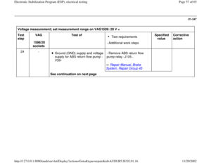
12 2 + 7 Activation of ABS
return flow pump relay
-J105-
0W
70
Electrical Wiring Diagrams,
Troubleshooting & Component Locations
- Check electrical wiring for short circuit
to Ground (GND) or B+. - If the electrical wiring is OK, replace
the relay.
Outlets on ABS control module -J104- differ depending on installed equipment
1) Vehicles with control module 4B0 907 389 2) Vehicles with control module 8D0 907 389/A/D/E
Pa
ge 24 of 65 Electronic Stabilization Pro
gram
(ESP
), electrical testin
g
11/20/2002 htt
p://127.0.0.1:8080/audi/servlet/Dis
play?action=Goto&t
yp
e=re
pair&id=AUDI.B5.SU02.01.16


 -J104- Terminal
Connected to...
Terminal
81
Not assigned
-
82
Not assigned
-
83
Not assigned
-
84")
 Test
step VAG
1598/20
sockets Test of
Test
requirements
- Additional work
steps Sp")
 Test
step VAG
1598/20
sockets Test of
Test
requirements
- Additional work
steps Specified
value Corrective ac")
 Test
step VAG
1598/20
sockets Test of
Test
requirements
- Additional work
steps Specified
value Corrective ac")
 Vehicles with front-wheel-drive
Pa
ge 22 of 65 Electronic Stabilization Pro
gram
(ESP
), electrical testin
g
11/20/2002 htt
p://127.0.0.1:8080/audi/servlet/Dis
play?action=Goto&t
yp
e=re
pair&id")

Test
step VAG
1598/20
sockets Test of
Test
requirements
- Additional work
steps Specif")