Page 25 of 35
17-25
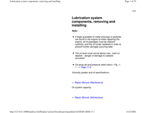
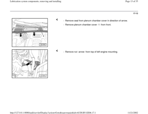
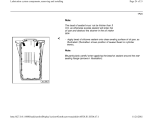
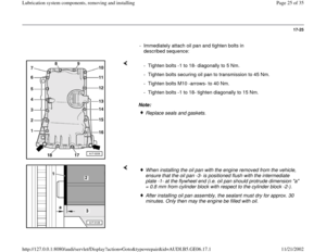
- Immediately attach oil pan and tighten bolts in
described sequence:
Note: - Tighten bolts -1 to 18- diagonally to 5 Nm.
- Tighten bolts securing oil pan to transmission to 45 Nm.
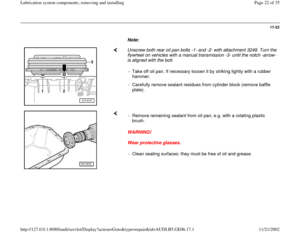
- Tighten bolts M10 -arrows- to 40 Nm.
- Tighten bolts -1 to 18- tighten diagonally to 15 Nm.
Replace seals and gaskets.
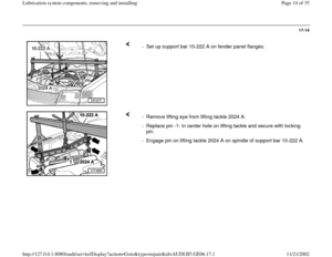
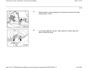
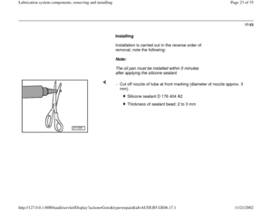
When installing the oil pan with the engine removed from the vehicle,
ensure that the oil pan -3- is positioned flush with the intermediate
plate -1- at the flywheel end (i.e. oil pan should protrude dimension "a"
= 0.8 mm from cylinder block with respect to the cylinder block -2-). After installing oil pan assembly, the sealant must dry for approx. 30
minutes. Only then may the engine be filled with oil.
Pa
ge 25 of 35 Lubrication s
ystem com
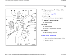
ponents, removin
g and installin
g
11/21/2002 htt
p://127.0.0.1:8080/audi/servlet/Dis
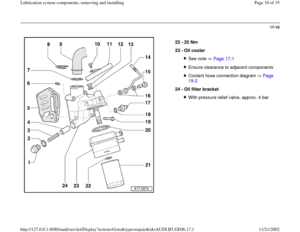
play?action=Goto&t
yp
e=re
pair&id=AUDI.B5.GE06.17.1
Page 26 of 35
17-26
Repair Manual, Suspension, Wheels, Steering, Repair Group 40
Vehicles with automatic transmission:
Repair Manual, 5 Spd. Automatic Transmission 01V, Repair Group 37
All models:
Vehicles with automatic transmission:
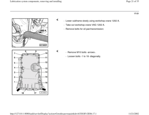
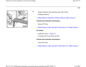
Repair Manual, 5 Spd. Automatic Transmission 01V, Repair Group 37 - Support subframe with workshop crane VAG 1202 A.
- Installing subframe:
- Secure ATF lines.- Install lock carrier Page 13
-1 .
- Fill engine with oil and check oil level.
- Check ATF level:
Pa
ge 26 of 35 Lubrication s
ystem com
ponents, removin
g and installin
g
11/21/2002 htt
p://127.0.0.1:8080/audi/servlet/Dis
play?action=Goto&t
yp
e=re
pair&id=AUDI.B5.GE06.17.1
Page 27 of 35
17-27
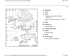
Tightening torques
Component
Nm
Oil pan to cylinder block M7 15
M10 40
Oil pan to transmission 45
Limit stop for torque reaction support on oil
pan
28
Engine mounting to subframe 25
Engine mounting to engine support 25
Transmission support to transmission
support M10 40
Transmission mounting to subframe
M8
25
Oil return pipe to oil pan 10
Oil drain plug 30
Hose clamps for air duct hoses
3.5
Pa
ge 27 of 35 Lubrication s
ystem com
ponents, removin
g and installin
g
11/21/2002 htt
p://127.0.0.1:8080/audi/servlet/Dis
play?action=Goto&t
yp
e=re
pair&id=AUDI.B5.GE06.17.1
Page 28 of 35
17-28
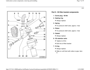
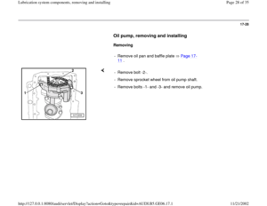
Oil pump, removing and installing
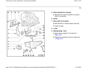
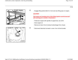
Removing
- Remove oil pan and baffle plate Page 17
-
11
.
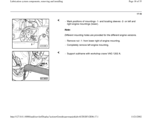
- Remove bolt -2-.
- Remove sprocket wheel from oil pump shaft.
- Remove bolts -1- and -3- and remove oil pump.
Pa
ge 28 of 35 Lubrication s
ystem com
ponents, removin
g and installin
g
11/21/2002 htt
p://127.0.0.1:8080/audi/servlet/Dis
play?action=Goto&t
yp
e=re
pair&id=AUDI.B5.GE06.17.1
Page 29 of 35
17-29
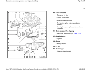
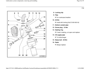
Installing
Installation is carried out in the reverse order of
removal; note the following:
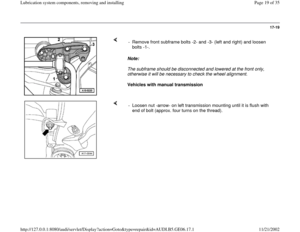
- Insert dowel sleeves -Item 12 -, Page 17
-4 on
top of oil pump.
Oil pump shaft/sprocket wheel location: Can
only be installed in one position.
- Installing oil pan Page 17
-23
Tightening torques
Component
Nm
Chain sprocket to oil pump shaft 22
Oil pump to cylinder block 16
Pa
ge 29 of 35 Lubrication s
ystem com
ponents, removin
g and installin
g
11/21/2002 htt
p://127.0.0.1:8080/audi/servlet/Dis
play?action=Goto&t
yp
e=re
pair&id=AUDI.B5.GE06.17.1
Page 30 of 35
17-30
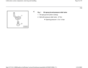
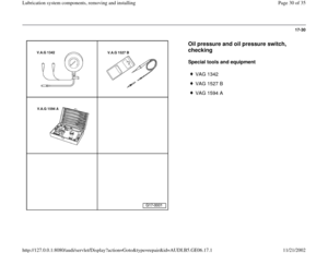
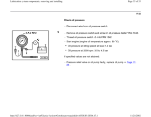
Oil pressure and oil pressure switch,
checking
Special tools and equipment
VAG 1342
VAG 1527 B
VAG 1594 A
Pa
ge 30 of 35 Lubrication s
ystem com
ponents, removin
g and installin
g
11/21/2002 htt
p://127.0.0.1:8080/audi/servlet/Dis
play?action=Goto&t
yp
e=re
pair&id=AUDI.B5.GE06.17.1
Page 31 of 35
17-31
Test requirements:
Oil level OK.
Engine oil temperature approx. 80 C.
Oil pressure warning lamp -K3- must come
on when ignition is switched on.
In vehicles with auto check system the "OK"
display must appear (call up symbol).
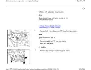
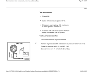
Testing oil pressure switch
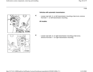
- Disconnect wire from oil pressure switch.
- Remove oil pressure switch and screw in oil pressure tester VAG 1342.
- Thread oil pressure switch -2- intoVAG 1342.
- Connect brown wire -1- of tester to Ground (-).
Pa
ge 31 of 35 Lubrication s
ystem com
ponents, removin
g and installin
g
11/21/2002 htt
p://127.0.0.1:8080/audi/servlet/Dis
play?action=Goto&t
yp
e=re
pair&id=AUDI.B5.GE06.17.1
Page 32 of 35
17-32
- Connect voltage tester VAG 1527 B to oil
pressure switch and positive side of battery (+)
using test leads from VAG 1594 A.
Test lamp should not light up.
- If test lamp lights up, install new oil pressure
switch.
- Start engine.
Note:
The switching point of the oil pressure switch can
be reached when the engine is cranked on the
starter motor, so watch the tester and the test
lamp while starting the engine.
Black oil pressure switch:
LED must light up at 1.2 to 1.6 bar.
- If test lamp does not light up, install new oil
pressure switch.
Pa
ge 32 of 35 Lubrication s
ystem com
ponents, removin
g and installin
g
11/21/2002 htt
p://127.0.0.1:8080/audi/servlet/Dis
play?action=Goto&t
yp
e=re
pair&id=AUDI.B5.GE06.17.1


using test leads from VAG 1594 A.
Test lamp should not light up.
- If test la")