Page 9 of 41
26-9
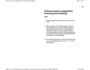
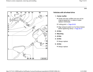
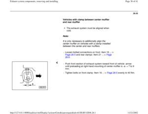
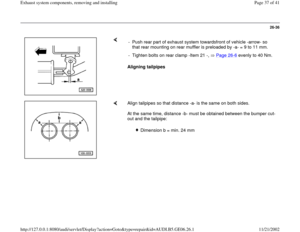
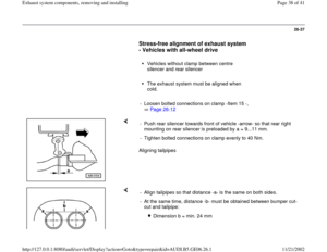
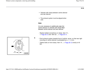
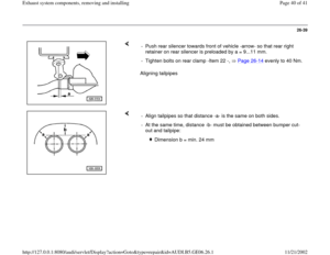
Vehicles with all-wheel drive
1 -
Center muffler
Center and rear mufflers are one unit as
original equipment. In cases of repair
replace individually Cutting point Page 26
-20
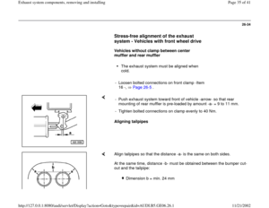
Align exhaust system so it is free of stress
before tightening clamp Page 26
-37
2 -
25 Nm
3 -
Mounting
4 -
25 Nm
5 -
25 Nm
Always replace
6 -
30 Nm Always replace
Pa
ge 9 of 41 Exhaust s
ystem com
ponents, removin
g and installin
g
11/21/2002 htt
p://127.0.0.1:8080/audi/servlet/Dis
play?action=Goto&t
yp
e=re
pair&id=AUDI.B5.GE06.26.1
Page 10 of 41
26-10
Repair Manual, 1.8 Liter 4
-Cyl. 5V Turbo Fuel
Injection & Ignition, Engine Code(s): AWM, Repair Group 24
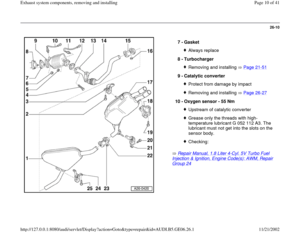
7 -
Gasket Always replace
8 -
Turbocharger Removing and installing Page 21
-51
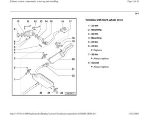
9 -
Catalytic converter
Protect from damage by impactRemoving and installing Page 26
-27
10 -
Oxygen sensor - 55 Nm
Upstream of catalytic converterGrease only the threads with high-
temperature lubricant G 052 112 A3. The
lubricant must not get into the slots on the
sensor body. Checking:
Pa
ge 10 of 41 Exhaust s
ystem com
ponents, removin
g and installin
g
11/21/2002 htt
p://127.0.0.1:8080/audi/servlet/Dis
play?action=Goto&t
yp
e=re
pair&id=AUDI.B5.GE06.26.1
Page 11 of 41
26-11
Repair Manual, 1.8 Liter 4
-Cyl. 5V Turbo Fuel
Injection & Ignition, Engine Code(s): AWM, Repair Group 24
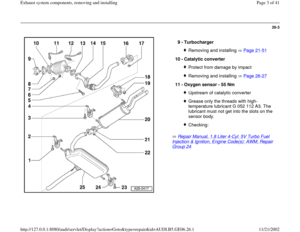
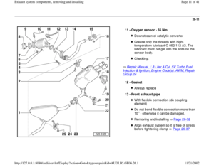
11 -
Oxygen sensor - 55 Nm Downstream of catalytic converterGrease only the threads with high-
temperature lubricant G 052 112 A3. The
lubricant must not get into the slots on the
sensor body. Checking:
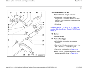
12 -
Gasket
Always replace
13 -
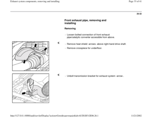
Front exhaust pipe With flexible connection (de coupling
element) Do not bend flexible connection more than
10 - otherwise it can be damaged. Removing and installing Page 26
-32
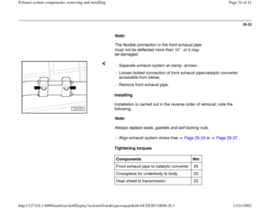
Align exhaust system so it is free of stress
before tightening clamp Page 26
-37
Pa
ge 11 of 41 Exhaust s
ystem com
ponents, removin
g and installin
g
11/21/2002 htt
p://127.0.0.1:8080/audi/servlet/Dis
play?action=Goto&t
yp
e=re
pair&id=AUDI.B5.GE06.26.1
Page 12 of 41
26-12
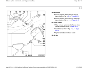
14 -
Mounting
Individual parts of mounting for manual
transmission Fig. 3
, Page 26
-16
Individual parts of mounting for automatic
transmission Fig. 4
, Page 26
-17
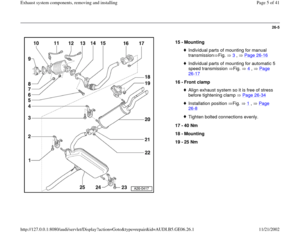
15 -
Front clamp
Align exhaust system so it is free of stress
before tightening clamp Page 26
-37
Installation position Fig. 1
, Page
26
-15
Tighten bolted connections evenly
16 -
40 Nm
Pa
ge 12 of 41 Exhaust s
ystem com
ponents, removin
g and installin
g
11/21/2002 htt
p://127.0.0.1:8080/audi/servlet/Dis
play?action=Goto&t
yp
e=re
pair&id=AUDI.B5.GE06.26.1
Page 13 of 41
26-13
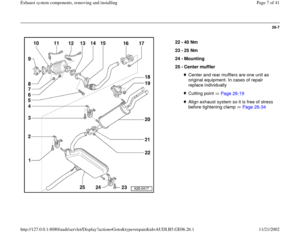
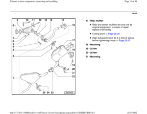
17 -
Rear muffler
Rear and center mufflers are one unit as
original equipment. In cases of repair
replace individually Cutting point Page 26
-20
Align exhaust system so it is free of stress
before tightening clamp Page 26
-37
18 -
Mounting
19 -
25 Nm
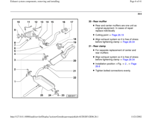
20 -
25 Nm
21 -
Mounting
Pa
ge 13 of 41 Exhaust s
ystem com
ponents, removin
g and installin
g
11/21/2002 htt
p://127.0.0.1:8080/audi/servlet/Dis
play?action=Goto&t
yp
e=re
pair&id=AUDI.B5.GE06.26.1
Page 14 of 41
26-14
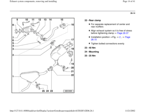
22 -
Rear clamp
For separate replacement of center and
rear mufflers Align exhaust system so it is free of stress
before tightening clamp Page 26
-37
Installation position Fig. 2
, Page
26
-15
Tighten bolted connections evenly
23 -
40 Nm
24 -
Mounting
25 -
25 Nm
Pa
ge 14 of 41 Exhaust s
ystem com
ponents, removin
g and installin
g
11/21/2002 htt
p://127.0.0.1:8080/audi/servlet/Dis
play?action=Goto&t
yp
e=re
pair&id=AUDI.B5.GE06.26.1
Page 15 of 41
26-15
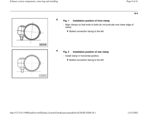
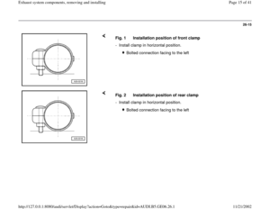
Fig. 1 Installation position of front clamp
- Install clamp in horizontal position.
Bolted connection facing to the left
Fig. 2 Installation position of rear clamp
- Install clamp in horizontal position.
Bolted connection facing to the left
Pa
ge 15 of 41 Exhaust s
ystem com
ponents, removin
g and installin
g
11/21/2002 htt
p://127.0.0.1:8080/audi/servlet/Dis
play?action=Goto&t
yp
e=re
pair&id=AUDI.B5.GE06.26.1
Page 16 of 41
26-16
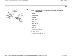
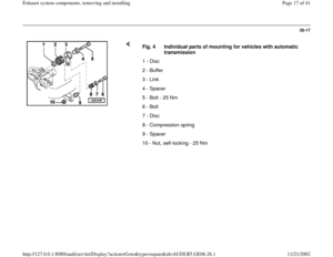
Fig. 3 Individual parts of mounting for vehicles with manual
transmission
1 - Buffer
2 - Spacer pipe
3 - Washer
4 - Lug, right
5 - Disc
6 - Bolt - 25 Nm
7 - Spacer
8 - Lug, left
9 - Compression spring
10 - Bolt - 25 Nm
11 - Nut, self-locking - 25 Nm
Pa
ge 16 of 41 Exhaust s
ystem com
ponents, removin
g and installin
g
11/21/2002 htt
p://127.0.0.1:8080/audi/servlet/Dis
play?action=Goto&t
yp
e=re
pair&id=AUDI.B5.GE06.26.1

: AWM, Repair Group 24
7 -
Gasket Always replace
8 -
Turbocharger Removing and installing Page 2")
: AWM, Repair Group 24
11 -
Oxygen sensor - 55 Nm Downstream of catalytic converterGrease only the")


