Page 9 of 78
24-7
5 -
Secondary Air Injection (AIR) solenoid
valve -N112-
6 -
Intake Air Temperature (IAT) sensor -G42-
7 -
4-pin harness connector
for Heated Oxygen Sensor (HO2S) 2 -
G108- before catalytic converter and
Oxygen Sensor (O2S) 2 Heater -Z28-
(bank 2 sensor 1) Black
8 -
3-pin harness connector for engine speed (RPM) sensor -G28-gray
9 -
3-pin harness connector for Knock Sensor (KS) 2 -G66-blue
Pa
ge 9 of 78 Motronic in
jection s
ystem, servicin
g
11/23/2002 htt
p://127.0.0.1:8080/audi/servlet/Dis
play?action=Goto&t
yp
e=re
pair&id=AUDI.B5.FU05.24.1
Page 10 of 78
24-8
10 -
E-box in plenum chamber
Motronic Engine Control Module (ECM) -
J220- Secondary Air Injection (AIR) Pump Relay -
J299- Fig. 10
, page Page 24
-12
11 -
Valve -2- for camshaft adjustment -N208-
12 -
Camshaft Position (CMP) sensor 2 -G163-
Bank 1
13 -
Heated Oxygen Sensor (HO2S) -G39-
before catalytic converter with Oxygen
Sensor (O2S) Heater -Z19- Bank 1, sensor 1
14 -
Ground connection on the engine bracket, right side
15 -
Mass Air Flow (MAF) sensor -G70- Checking Page 24
-56
16 -
Evaporative Emission (EVAP) canister
purge regulator valve -N80-
Pa
ge 10 of 78 Motronic in
jection s
ystem, servicin
g
11/23/2002 htt
p://127.0.0.1:8080/audi/servlet/Dis
play?action=Goto&t
yp
e=re
pair&id=AUDI.B5.FU05.24.1
Page 11 of 78
24-9
17 -
Engine Coolant Temperature (ECT) sensor
-G62-
for Engine Control Module (ECM)At coolant line behind cylinder head engine
bank 1 with Engine Coolant Temperature (ECT)
Sensor -G2- Checking Page 28
-23
If necessary, release pressure in cooling
system before removing
18 -
Throttle valve control module -J338- With throttle drive (power accelerator
actuation) -G186-, angle sensor -1- for
throttle drive (power accelerator actuation)
-G187-, and angle sensor -2- for throttle
drive (power accelerator actuation) -G188-
19 -
Intake Manifold Change-Over Valve -N156-
20 -
Fuel pressure regulator
21 -
Engine Speed (RPM) sensor -G28- in transmission housing via ring gearChecking Page 28
-19
Pa
ge 11 of 78 Motronic in
jection s
ystem, servicin
g
11/23/2002 htt
p://127.0.0.1:8080/audi/servlet/Dis
play?action=Goto&t
yp
e=re
pair&id=AUDI.B5.FU05.24.1
Page 12 of 78
24-10
22 -
Camshaft Position (CMP) sensor 2 -G40-
Bank 2
23 -
Heated Oxygen Sensor (HO2S) 2 -G108-
before catalytic converter with Oxygen
Sensor (O2S) 2 Heater -Z28- Bank 2, sensor 1
24 -
Knock Sensor (KS) 2 -G66-
25 -
Ignition coils (-N-, -N128-, -N158-) with power output stage -N122-
26 -
Knock Sensor (KS) 1 -G61-
27 -
Fuel injectors -N30- through -N33-
,Cylinder 5/6 Fuel Injector -N83-, -N84-
28 -
Valve -1- for camshaft adjustment -N205-
29 -
Secondary Air Injection (AIR) pump
motor-V101-
Pa
ge 12 of 78 Motronic in
jection s
ystem, servicin
g
11/23/2002 htt
p://127.0.0.1:8080/audi/servlet/Dis
play?action=Goto&t
yp
e=re
pair&id=AUDI.B5.FU05.24.1
Page 13 of 78
24-11
Fig. 7 Component location, fault light for power accelerator
activation -K132-
Fig. 8 Installation position, Throttle Position (TP) sensor -G79-
and sender 2 for accelerator pedal position -G185-
Pa
ge 13 of 78 Motronic in
jection s
ystem, servicin
g
11/23/2002 htt
p://127.0.0.1:8080/audi/servlet/Dis
play?action=Goto&t
yp
e=re
pair&id=AUDI.B5.FU05.24.1
Page 14 of 78
24-12
Note:
In order to assure sufficiently secure fitting, switches must not be installed
more than once.
Adjusting switch:
Repair Manual, Brake System, ABS, ABS/EDL, Repair Group 46
Fig. 9 Component location Brake Light Switch -F- and Brake
Vacuum Vent Valve Switch For Cruise Control/Diesel Fuel
Injection, Clutch Vacuum Vent Valve Switch -F36-
1 - Clip
2 - Brake Light Switch -F-, Brake Vacuum Vent Valve Switch For Cruise
Control/Diesel Fuel Injection -F47-
3 - Clutch vacuum vent valve switch -F36-
Secondary Air Injection (AIR) Pump Relay -J299- (arrow) in 3-pin relay
carrier in E-box, plenum chamber. Fig. 10 Component location for Secondary Air Injection (AIR)
Pump Relay -J299-
Pa
ge 14 of 78 Motronic in
jection s
ystem, servicin
g
11/23/2002 htt
p://127.0.0.1:8080/audi/servlet/Dis
play?action=Goto&t
yp
e=re
pair&id=AUDI.B5.FU05.24.1
Page 15 of 78
24-13
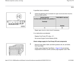
Fuel Pump (FP) Relay -J17- is located at position 4 of central electrics in
driver's footwell, left. Fig. 11 Component locations Fuel Pump (FP) Relay -J17-
Data Link Connector (DLC) in knee bolster on driver's side. Fig. 12 Component location of Data Link Connector (DLC)
Pa
ge 15 of 78 Motronic in
jection s
ystem, servicin
g
11/23/2002 htt
p://127.0.0.1:8080/audi/servlet/Dis
play?action=Goto&t
yp
e=re
pair&id=AUDI.B5.FU05.24.1
Page 16 of 78
24-14
Air filter, disassembling and assembling
1 -
Cover
2 -
Air duct
to metering unit
3 -
Mass Air Flow (MAF) sensor -G70-
4 -
10 Nm
5 -
Connection hose
6 -
Seal
7 -
Air filter, upper portion
8 -
Rubber grommet
9 -
Filter element
10 -
Air filter, lower portion
Pa
ge 16 of 78 Motronic in
jection s
ystem, servicin
g
11/23/2002 htt
p://127.0.0.1:8080/audi/servlet/Dis
play?action=Goto&t
yp
e=re
pair&id=AUDI.B5.FU05.24.1


 solenoid
valve -N112-
6 -
Intake Air Temperature (IAT) sensor -G42-
7 -
4-pin harness connector
for Heated Oxygen Sensor (HO2S) 2 -
G108- before cata")
 -
J220- Secondary Air Injection (AIR) Pump Relay -
J299- Fig. 10
, page Page 24
-12
11 -
Valve -2- for camshaft ad")
 sensor
-G62-
for Engine Control Module (ECM)At coolant line behind cylinder head engine
bank 1 with Engine Coolant Temperature (ECT)
Sensor -G2- Ch")
 sensor 2 -G40-
Bank 2
23 -
Heated Oxygen Sensor (HO2S) 2 -G108-
before catalytic converter with Oxygen
Sensor (O2S) 2 Heater -Z28- Bank 2, sensor 1
24 -
K")
 sensor -G79-
and sender 2 for accelerator ped")

 Relay -J17- is located at position 4 of central electrics in
drivers footwell, left. Fig. 11 Component locations Fuel Pump (FP) Relay -J17-
Data Link Connector (DL")
 sensor -G70-
4 -
10 Nm
5 -
Connection hose
6 -
Seal
7 -
Air filter, u")