Page 9 of 64
28-8
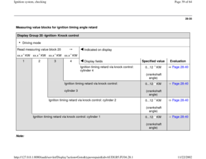
If malfunction remains at the same cylinder.
- Disconnect harness connector from ignition
coil.
Electrical Wiring Diagrams, Troubleshooting & Component Locations
If the Ground (GND) connection is OK. - Check Ground (GND) connection between socket 4a and engine
Ground (GND) for open circuit and short circuit to B+. - Repair any open/short circuit as necessary.
- Connect hand-held multimeter (voltage range) to terminal 15 of
harness connector and Ground (GND).
- Disconnect harness connector from fuel injector of cylinder to be
tested.
- Operate starter.
Specified value: approx. battery voltage
Pa
ge 9 of 64 I
gnition s
ystem, checkin
g
11/22/2002 htt
p://127.0.0.1:8080/audi/servlet/Dis
play?action=Goto&t
yp
e=re
pair&id=AUDI.B5.FU04.28.1
Page 10 of 64
28-9
If the specification is not obtained:
- Check wiring.
Electrical Wiring Diagrams, Troubleshooting &
Component Locations If the specification is obtained:
- Disconnect 3-pin harness connectors on power
output stages for ignition coils; component
locations overview Page 24
-5 .
- Then connect diode test lamp to 3-pin
connectors for both output stages.
If the specifications are not obtained: - Connect diode test lamp VAG1527 to following contacts on connectors
for power output stages: 3-pin harness connector
terminal
Specification
(with starter activated)
1 + Ground (GND) Diode test lamp should
2 + Ground (GND) light up
3 + Ground (GND)
Pa
ge 10 of 64 I
gnition s
ystem, checkin
g
11/22/2002 htt
p://127.0.0.1:8080/audi/servlet/Dis
play?action=Goto&t
yp
e=re
pair&id=AUDI.B5.FU04.28.1
Page 11 of 64
- Switch ignition off.
Pa
ge 11 of 64 I
gnition s
ystem, checkin
g
11/22/2002 htt
p://127.0.0.1:8080/audi/servlet/Dis
play?action=Goto&t
yp
e=re
pair&id=AUDI.B5.FU04.28.1
Page 12 of 64
28-10
Check the following wiring connections for open circuits and/or short to B+
or Ground (GND).
Black 3-pin connector on power
output stage, terminal
3-pin connector on ignition
coil, terminal
1 1 (cylinder 1)
2 1 (cylinder 2)
3 1 (cylinder 3)
Brown 3-pin connector on power
output stage, terminal
3-pin connector on ignition
coil, terminal
1 1 (cylinder 4)
2 1 (cylinder 5)
3 1 (cylinder 6)
- Eliminate any open/short circuit as necessary.
Pa
ge 12 of 64 I
gnition s
ystem, checkin
g
11/22/2002 htt
p://127.0.0.1:8080/audi/servlet/Dis
play?action=Goto&t
yp
e=re
pair&id=AUDI.B5.FU04.28.1
Page 13 of 64
28-11
Power output stages for ignition coils,
checking
Note:
Power Output Stage -N122 (black connector)
activates the ignition coils for cylinder bank 1
(cylinders 1 to 3).
Power Output Stage 2 -N192 (brown connector)
activates the ignition coils for cylinder bank 2
(cylinders 4 to 6).
Checking activation of power output stages
- Disconnect harness connectors from all six fuel
injectors.
Note:
It is important to ensure that no fuel is injected
during the test as this would damage the catalytic
converter. The harness connectors on the fuel
injectors must therefore be disconnected.
Pa
ge 13 of 64 I
gnition s
ystem, checkin
g
11/22/2002 htt
p://127.0.0.1:8080/audi/servlet/Dis
play?action=Goto&t
yp
e=re
pair&id=AUDI.B5.FU04.28.1
Page 14 of 64
28-12
- Disconnect 4-pin harness connectors on power
output stages Component locations overview,
Page 24
-5 .
- Connect diode test lamp VAG1527 in turn to the following contacts on
the two 4-pin connectors for the power output stages.
- Then, operate starter for a few seconds.
6-pin connector on wiring harness,
terminal
Specification
1 + Ground (GND) Diode test lamp
should
3 + Ground (GND) flash (brief impulse)
4 + Ground (GND)
Pa
ge 14 of 64 I
gnition s
ystem, checkin
g
11/22/2002 htt
p://127.0.0.1:8080/audi/servlet/Dis
play?action=Goto&t
yp
e=re
pair&id=AUDI.B5.FU04.28.1
Page 15 of 64
28-13
If the specifications are not obtained:
- Switch ignition off.
- Connect test box VAG 1598/31 to wiring
harness for engine control module. Do not
connect to the engine control module itself.
Page 24
-20
.
The following wiring connections are to be checked for open circuits
and/or short to B+ or Ground (GND).
Black 4-pin connector on wiring
harness, terminal VAG1598/31 test box,
socket
1 94
3 110
4 102 Brown 4-pin connector on wiring
harness, terminal VAG1598/31 test box,
socket
1 95
3 111
4 103
Pa
ge 15 of 64 I
gnition s
ystem, checkin
g
11/22/2002 htt
p://127.0.0.1:8080/audi/servlet/Dis
play?action=Goto&t
yp
e=re
pair&id=AUDI.B5.FU04.28.1
Page 16 of 64
28-14
- Rectify any open/short circuit as necessary.
If no wiring malfunction is detected:
- Connect 4-pin connectors to power output
stages.
- Disconnect 3-pin connectors from power output
stages.
- Connect diode test lamp VAG1527 to battery
(B+) and to one of the 3 terminals on power
output stage.
- Operate starter for few seconds.
The diode test lamp should flash.
- Carry out test with all 3 terminals on each of the
3-pin connectors for the power output stages.
The diode test lamp should flash each time.
Pa
ge 16 of 64 I
gnition s
ystem, checkin
g
11/22/2002 htt
p://127.0.0.1:8080/audi/servlet/Dis
play?action=Goto&t
yp
e=re
pair&id=AUDI.B5.FU04.28.1


.
Black 3-pin connector on power
output stage, terminal
3-pin connector on ignition
coil,")

activates the ignition coils for cylinder bank 1
(cylinders 1 to 3).")


