Page 17 of 26
13-30
Note:
The needle bearing is located in the flywheel and
must be pressed in if a new flywheel is installed
Page 13
-35
.
Installing
- Install dual-mass flywheel.
Note:
Always replace flywheel securing bolts.
- Install clutch.
Repair Manual, 6 Spd. Manual Transmission
01E, Repair Group 30
- Install transmission.
Repair Manual, 6 Spd. Manual Transmission
01E, Repair Group 34
Pa
ge 17 of 26 C
ylinder block, crankshaft and fl
ywheel, disassembl
y and assembl
y
11/21/2002 htt
p://127.0.0.1:8080/audi/servlet/Dis
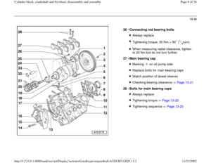
play?action=Goto&t
yp
e=re
pair&id=AUDI.B5.GE05.13.2
Page 18 of 26
13-31
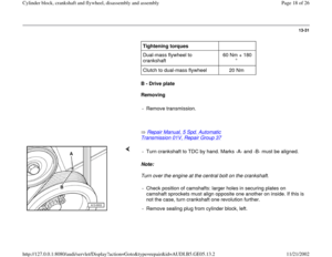
Tightening torques
Dual-mass flywheel to
crankshaft 60 Nm + 180
Clutch to dual-mass flywheel 20 Nm
B - Drive plate
Removing
- Remove transmission.
Repair Manual, 5 Spd. Automatic
Transmission 01V, Repair Group 37
Note:
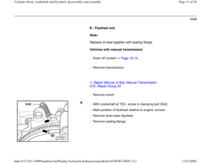
Turn over the engine at the central bolt on the crankshaft. - Turn crankshaft to TDC by hand. Marks -A- and -B- must be aligned.
- Check position of camshafts: larger holes in securing plates on
camshaft sprockets must align opposite one another on inside. If this is
not the case, turn crankshaft one revolution further.
- Remove sealing plug from cylinder block, left.
Pa
ge 18 of 26 C
ylinder block, crankshaft and fl
ywheel, disassembl
y and assembl
y
11/21/2002 htt
p://127.0.0.1:8080/audi/servlet/Dis
play?action=Goto&t
yp
e=re
pair&id=AUDI.B5.GE05.13.2
Page 19 of 26
13-32
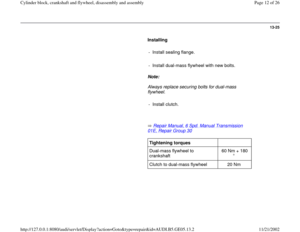
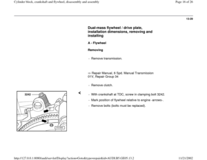
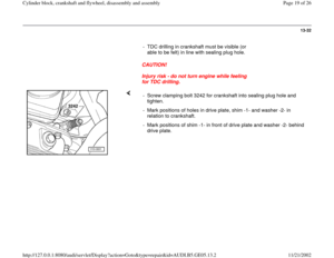
- TDC drilling in crankshaft must be visible (or
able to be felt) in line with sealing plug hole.
CAUTION!
Injury risk - do not turn engine while feeling
for TDC drilling.
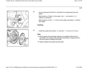
- Screw clamping bolt 3242 for crankshaft into sealing plug hole and
tighten.
- Mark positions of holes in drive plate, shim -1- and washer -2- in
relation to crankshaft.
- Mark positions of shim -1- in front of drive plate and washer -2- behind
drive plate.
Pa
ge 19 of 26 C
ylinder block, crankshaft and fl
ywheel, disassembl
y and assembl
y
11/21/2002 htt
p://127.0.0.1:8080/audi/servlet/Dis
play?action=Goto&t
yp
e=re
pair&id=AUDI.B5.GE05.13.2
Page 20 of 26
13-33
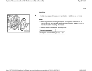
Installing
Note: - Install drive plate with washer -2- and shim -1- (3.0 mm or 4.0 mm).
Short engines and exchange engines are supplied without bush in
crankshaft. On vehicles with automatic transmission, always knock in
new bush before installing drive plate. Always replace drive plate securing bolts.
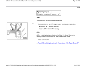
Tightening torques
Drive plate to crankshaft
60 Nm + 90
Pa
ge 20 of 26 C
ylinder block, crankshaft and fl
ywheel, disassembl
y and assembl
y
11/21/2002 htt
p://127.0.0.1:8080/audi/servlet/Dis
play?action=Goto&t
yp
e=re
pair&id=AUDI.B5.GE05.13.2
Page 21 of 26
13-34
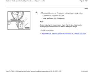
Note:
Before installing the transmission, check that the dowel sleeves for
locating engine/transmission are fitted in the engine flange.
Repair Manual, 5 Spd. Automatic Transmission 01V, Repair Group 37
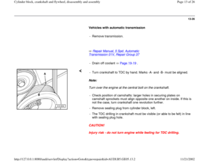
- Measure distance -a- at three points and calculate average value.
Distance -a- = approx. 12.3 mm.
- Install a different shim if necessary.
- Install transmission.
Pa
ge 21 of 26 C
ylinder block, crankshaft and fl
ywheel, disassembl
y and assembl
y
11/21/2002 htt
p://127.0.0.1:8080/audi/servlet/Dis
play?action=Goto&t
yp
e=re
pair&id=AUDI.B5.GE05.13.2
Page 22 of 26
13-35
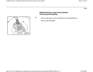
Needle bearing in dual-mass flywheel,
removing and installing
- Pull out with puller, such as KUKKO 21/2 and KUKKO 22-1.
- Drive in with drift 3264.
Pa
ge 22 of 26 C
ylinder block, crankshaft and fl
ywheel, disassembl
y and assembl
y
11/21/2002 htt
p://127.0.0.1:8080/audi/servlet/Dis
play?action=Goto&t
yp
e=re
pair&id=AUDI.B5.GE05.13.2
Page 23 of 26
13-36
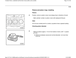
Pistons and piston rings, installing
Pistons
Position: arrow on piston crown must always face in direction of travel.
Note:
Do not use a center-punch or similar, as pistons have a special coating.
Checking piston diameter - Mark cylinder number on piston crown with waterproof felt pen.
-
Measure pistons approx. 10 mm from bottom of skirt, at 90 to piston
pin axis.
Difference between actual and nominal diameter: not more than
0.04 mm.
Pa
ge 23 of 26 C
ylinder block, crankshaft and fl
ywheel, disassembl
y and assembl
y
11/21/2002 htt
p://127.0.0.1:8080/audi/servlet/Dis
play?action=Goto&t
yp
e=re
pair&id=AUDI.B5.GE05.13.2
Page 24 of 26
13-37
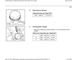
Ring-to-groove clearance Clearance when new
Wear limit
0.02 ... 0.08 mm 0.10 mm
Checking piston ring gap
- Push ring in squarely to a position approx. 15 mm from bottom end of
cylinder. Piston ring
Gap when new
Wear limit
1 0.35 ... 0.50 mm 1.0 mm
2 0.50 ... 0.70 mm 1.4 mm
3 0.25 ... 0.50 mm 0.8 mm
Pa
ge 24 of 26 C
ylinder block, crankshaft and fl
ywheel, disassembl
y and assembl
y
11/21/2002 htt
p://127.0.0.1:8080/audi/servlet/Dis
play?action=Goto&t
yp
e=re
pair&id=AUDI.B5.GE05.13.2


 in line with sealing plug hole.
CAUTION!
Injury risk - do not turn engine while feeling
for TDC drilling")
.
Short engines and exchange engines are supplied without bush in
crankshaft. On vehicles w")


