Page 9 of 22
Read safety precautions for test driving vehicles
while using test equipment page 24
-9 .
The speed signal is generated by the vehicle
speed sensor (at the transmission), and
processed at the speedometer/odometer in the
instrument cluster.
Pa
ge 9 of 22 Auxiliar
y si
gnals, checkin
g
11/23/2002 htt
p://127.0.0.1:8080/audi/servlet/Dis
play?action=Goto&t
yp
e=re
pair&id=AUDI.B5.FU03.24.4
Page 10 of 22
24-169
Test procedure
- Connect VAG1551 or VAG1552 scan tool and
press buttons -0- and -1- to insert "Engine
Electronics" address word 01 (with engine
running at idle) page 01
-8 .
Rapid data transfer
HELP
Select function XX
Indicated on display
- Press buttons -0- and -8- to select "Read Measuring Value Block"
function 08, and press -Q- button to confirm input.
Read Measurin
g Value Block
HELP
Input displa
y group number XXX
Indicated on display
- Press buttons -0-, -0- and -5- to input display group number 5 (005),
and press -Q- button to confirm input.
Read Measuring Value Block 5 1 2 3 4
Indicated on display (1-4 = display fields)
- Road test and compare indicated vehicle speed with value in display
field 3 (2nd technician required, Safety precautions page 24
-9 ).
Pa
ge 10 of 22 Auxiliar
y si
gnals, checkin
g
11/23/2002 htt
p://127.0.0.1:8080/audi/servlet/Dis
play?action=Goto&t
yp
e=re
pair&id=AUDI.B5.FU03.24.4
Page 11 of 22
24-170
Display fields
1 2 3 4
Display group 5: General engine data
Display xxx RPM xx.xx ms xxx km/h Idle
Part throt
Full throt
Decel
Enrich
Indicates Engine speed
(in 40 RPM
steps) Engine load Vehicle speed Operating
condition
Range 0 - 6800 RPM 0.00 - 12.75
ms 0 - 326 km/h ---
Specified
value --- --- Approx. vehicle speed ---
--- --- If no vehicle speed is displayed page 24
-171
,
Continuation
---
If displayed value is OK:
-
Press button.
Pa
ge 11 of 22 Auxiliar
y si
gnals, checkin
g
11/23/2002 htt
p://127.0.0.1:8080/audi/servlet/Dis
play?action=Goto&t
yp
e=re
pair&id=AUDI.B5.FU03.24.4
Page 12 of 22
- Press buttons -0- and -6- to select "End Output"
function 06, and press -Q- button to confirm
input.
- Switch off ignition.
Pa
ge 12 of 22 Auxiliar
y si
gnals, checkin
g
11/23/2002 htt
p://127.0.0.1:8080/audi/servlet/Dis
play?action=Goto&t
yp
e=re
pair&id=AUDI.B5.FU03.24.4
Page 13 of 22

24-171
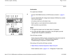
Continuation
If no speed was indicated:
Notes:
If the LED does not blink:
If the wiring is OK and the LED does not blink:
Repair Manual, Electrical Equipment, Repair Group 90
- Connect VAG1598/22 test box to ECM harness connector page 01
-
67
.
- Connect VAG1527B LED voltage tester between ECM/test box sockets
3 (B+) and 20 (signal).
- Lift vehicle at left-front until wheel is free.
- Switch ignition on and rotate left-front wheel by hand.
LED must blink (very brief blink)
The right-front wheel must not rotate; block it if necessary.For LEDs with little voltage consumption, the LED lights up at half
strength when the ignition is switched on.
- Check wiring from ECM connector, terminal 20 to instrument cluster for
open circuit or short circuit Electrical Wiring Diagrams,
Troubleshooting & Component Locations binder.
-
Check readiness code page 01
-70
. If Diagnostic Trouble Code
Pa
ge 13 of 22 Auxiliar
y si
gnals, checkin
g
11/23/2002 htt
p://127.0.0.1:8080/audi/servlet/Dis
play?action=Goto&t
yp
e=re
pair&id=AUDI.B5.FU03.24.4
Page 14 of 22
(DTC) memory has been erased, or ECM was disconnected, generate
new readiness code page 01
-73
.
Pa
ge 14 of 22 Auxiliar
y si
gnals, checkin
g
11/23/2002 htt
p://127.0.0.1:8080/audi/servlet/Dis
play?action=Goto&t
yp
e=re
pair&id=AUDI.B5.FU03.24.4
Page 15 of 22
24-172
CAN-Bus, checking
When a CAN-Bus malfunction is indicated during
a check of DTC memory of the Engine Control
Module (ECM), refer to the following test to
eliminate the malfunction.
Note:
The information exchange occurs between the
Engine Control Module (ECM) and the
Transmission Control Module (TCM) via a CAN-
Bus.
All signals are carried by 2 wires between the
ECM and the TCM.
Required special tools and test equipment
VAG1551 or VAG1552 Scan Tool (ST) with
VAG1551/3 adapter cable
VAG1598/22 test box
VW1594 connector test kit
Wiring diagrams
Pa
ge 15 of 22 Auxiliar
y si
gnals, checkin
g
11/23/2002 htt
p://127.0.0.1:8080/audi/servlet/Dis
play?action=Goto&t
yp
e=re
pair&id=AUDI.B5.FU03.24.4
Page 16 of 22
24-173
Checking
- Check DTC memory of Transmission Control
Module (TCM).
Repair Manual, 5 Spd. Automatic
Transmission 01V, Repair Group 01 If a DTC regarding the CAN-Bus wire is also
stored in the TCM:
- Switch ignition off.
Electrical Wiring Diagrams, Troubleshooting & Component Locations
binder
If wiring is OK: - Connect VAG1598/22 test box to ECM harness connector page 01
-
67
.
- Check wires from terminal 29 and terminal 41 of test box to
transmission control module for open or short circuit per wiring
diagram. - Replace Transmission Control Module (TCM) and Engine Control
Module (ECM) as necessary and in sequence.
Pa
ge 16 of 22 Auxiliar
y si
gnals, checkin
g
11/23/2002 htt
p://127.0.0.1:8080/audi/servlet/Dis
play?action=Goto&t
yp
e=re
pair&id=AUDI.B5.FU03.24.4


, and
process")
 page 01
-8")


 memory has been erased, or ECM was disconnected, generate
new readiness code page 01
-73
.
Pa
ge 14 of 22 Auxiliar
y si
gnals, checkin
g
11/23/2002 htt
p://127.0.0.1:8080/audi/servlet/Dis
p")
, refer to the following test to
eliminate the malfunc")
.
Repair Manual, 5 Spd. Automatic
Transmission 01V, Repair Group 01 If a DTC regarding the CAN-B")