Page 1 of 40
19-1
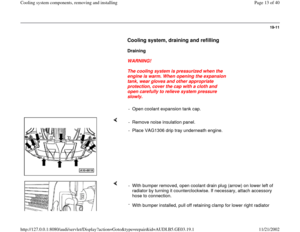
Cooling system components,
removing and installing
WARNING!
The cooling system is pressurized when the
engine is warm. When opening the expansion
tank, wear gloves and other appropriate
protection, cover the cap with a cloth and
open carefully to relieve system pressure
slowly.
Notes:
Hoses are secured with spring-type clips. If
servicing, only use the same type of spring-type
clip.
Parts catalog
VAG1921 pliers are recommended when
installing spring-type clips.
The O-rings installed at the quick-release
connections must be replaced if damaged or
leaking.
Seals and gaskets must always be replaced.
Pa
ge 1 of 40 Coolin
g system com
ponents, removin
g and installin
g
11/21/2002 htt
p://127.0.0.1:8080/audi/servlet/Dis
play?action=Goto&t
yp
e=re
pair&id=AUDI.B5.GE03.19.1
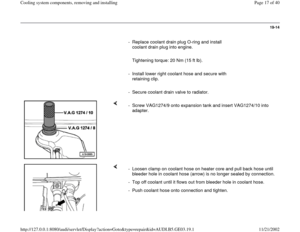
Page 2 of 40
When installing coolant hoses, make sure they
are free of stress and do not come into contact
with other components (the arrows which are
located on the coolant pipes and coolant hoses
must be opposite each other).
Perform cooling system leakage test using VAG
1274 cooling system tester and 1274/9 adapter.
Pa
ge 2 of 40 Coolin
g system com
ponents, removin
g and installin
g
11/21/2002 htt
p://127.0.0.1:8080/audi/servlet/Dis
play?action=Goto&t
yp
e=re
pair&id=AUDI.B5.GE03.19.1
Page 3 of 40
19-2
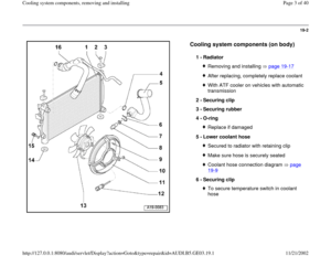
Cooling system components (on body)
1 -
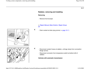
Radiator
Removing and installing page 19
-17
After replacing, completely replace coolantWith ATF cooler on vehicles with automatic
transmission
2 -
Securing clip
3 -
Securing rubber
4 -
O-ring Replace if damaged
5 -
Lower coolant hose Secured to radiator with retaining clipMake sure hose is securely seatedCoolant hose connection diagram page 19
-9
6 -
Securing clip
To secure temperature switch in coolant
hose
Pa
ge 3 of 40 Coolin
g system com
ponents, removin
g and installin
g
11/21/2002 htt
p://127.0.0.1:8080/audi/servlet/Dis
play?action=Goto&t
yp
e=re
pair&id=AUDI.B5.GE03.19.1
Page 4 of 40
19-3
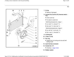
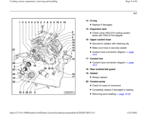
7 -
O-ring
Replace if damaged
8 -
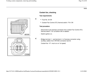
Coolant Fan Control (FC) thermal switch -
F18- 35 Nm (26 ft lb)For electric coolant fan
Switching temperatures, stage 1:On: 92-97 C (198-207 F)Off: 84-91 C (183-196 F)
Switching temperatures, stage 2:
On: 99-105 C (210-221 F)Off: 91-98 C (196-208 F)
9 -
Locking bolt
10 -
10 Nm (7 ft lb)
11 -
Fan ring
Clipped into air ducting and secured with
locking 9 bolt
12 -
2-pin harness connector
13 -
Coolant fan -V7- Checking page 19
-26
14 -
Rubber washer
Pa
ge 4 of 40 Coolin
g system com
ponents, removin
g and installin
g
11/21/2002 htt
p://127.0.0.1:8080/audi/servlet/Dis
play?action=Goto&t
yp
e=re
pair&id=AUDI.B5.GE03.19.1
Page 5 of 40
15 -
Coolant drain plug
10 Nm (7 ft lb)
Pa
ge 5 of 40 Coolin
g system com
ponents, removin
g and installin
g
11/21/2002 htt
p://127.0.0.1:8080/audi/servlet/Dis
play?action=Goto&t
yp
e=re
pair&id=AUDI.B5.GE03.19.1
Page 6 of 40
19-4
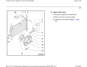
16 -
Upper coolant hose
Secured to radiator with retaining clipMake sure hose is securely seatedCoolant hose connection diagram page 19
-9
Pa
ge 6 of 40 Coolin
g system com
ponents, removin
g and installin
g
11/21/2002 htt
p://127.0.0.1:8080/audi/servlet/Dis
play?action=Goto&t
yp
e=re
pair&id=AUDI.B5.GE03.19.1
Page 7 of 40
19-5
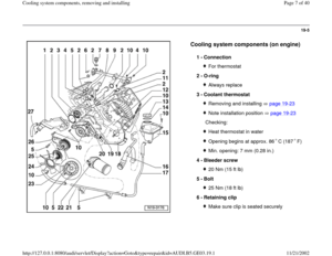
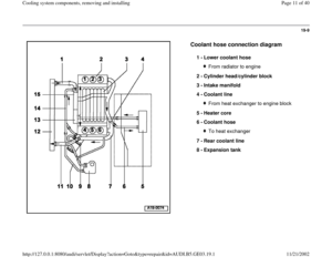
Cooling system components (on engine)
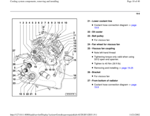
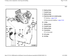
1 -
Connection
For thermostat
2 -
O-ring Always replace
3 -
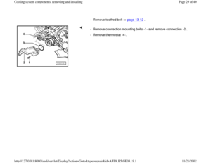
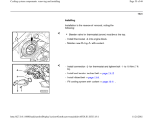
Coolant thermostat Removing and installing page 19
-23
Note installation position page 19
-23
Checking:
Heat thermostat in waterOpening begins at approx. 86 C (187 F)Min. opening: 7 mm (0.28 in.)
4 -
Bleeder screw 20 Nm (15 ft lb)
5 -
Bolt 25 Nm (18 ft lb)
6 -
Retaining clip Make sure clip is seated securely
Pa
ge 7 of 40 Coolin
g system com
ponents, removin
g and installin
g
11/21/2002 htt
p://127.0.0.1:8080/audi/servlet/Dis
play?action=Goto&t
yp
e=re
pair&id=AUDI.B5.GE03.19.1
Page 8 of 40
19-6
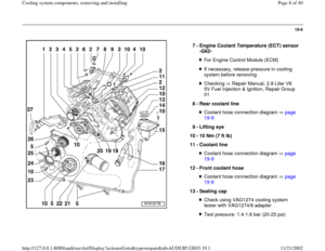
7 -
Engine Coolant Temperature (ECT) sensor
-G62-
For Engine Control Module (ECM)If necessary, release pressure in cooling
system before removing Checking Repair Manual, 2.8 Liter V6
5V Fuel Injection & Ignition, Repair Group
01
8 -
Rear coolant line
Coolant hose connection diagram page 19
-9
9 -
Lifting eye
10 -
10 Nm (7 ft lb)
11 -
Coolant line
Coolant hose connection diagram page 19
-9
12 -
Front coolant hose
Coolant hose connection diagram page 19
-9
13 -
Sealing cap
Check using VAG1274 cooling system
tester with VAG1274/8 adapter Test pressure: 1.4-1.6 bar (20-23 psi)
Pa
ge 8 of 40 Coolin
g system com
ponents, removin
g and installin
g
11/21/2002 htt
p://127.0.0.1:8080/audi/servlet/Dis
play?action=Goto&t
yp
e=re
pair&id=AUDI.B5.GE03.19.1


1 -
Radiator
Removing and installing page 19
-17
After replacing, completely replace coolantWith ATF cooler on vehicles with automatic
transmission")
 thermal switch -
F18- 35 Nm (26 ft lb)For electric coolant fan
Switching temperatures, stage 1:On: 92-97 C (198-207 F)Off: 84-")

Pa
ge 5 of 40 Coolin
g system com
ponents, removin
g and installin
g
11/21/2002 htt
p://127.0.0.1:8080/audi/servlet/Dis
play?action=Goto&t
yp
e=re
pair&id=AUD")


1 -
Connection
For thermostat
2 -
O-ring Always replace
3 -
Coolant thermostat Removing and installing page 19
-23
Note installation position")
 sensor
-G62-
For Engine Control Module (ECM)If necessary, release pressure in cooling
system before removing Checking Repair Manual, 2.8 Liter V6")