Page 25 of 35
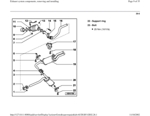
26-20
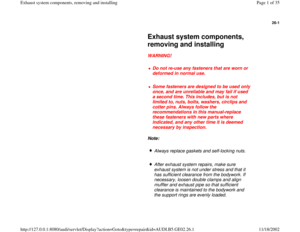
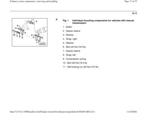
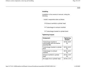
Installing
Installation is the reverse of removal, noting the
following:
- Install in sequential order as follows:
Exhaust manifold to cylinder head
Turbocharger to exhaust manifold
Turbocharger bracket to cylinder block
Tightening torques
Component
Tightening
torques
Turbocharger bracket to
turbocharger (bolt and washer
assembly M8) 40 Nm (30 ft
lb)
Turbocharger bracket to cylinder
block 45 Nm (33 ft
lb)
Turbocharger to exhaust
manifold 35 Nm (26 ft
lb)
Exhaust manifold to cylinder
head 25 Nm (18 ft
lb)
Oil supply line to cylinder head 20 Nm (15 ft
Pa
ge 25 of 35 Exhaust s
ystem com
ponents, removin
g and installin
g
11/18/2002 htt
p://127.0.0.1:8080/audi/servlet/Dis
play?action=Goto&t
yp
e=re
pair&id=AUDI.B5.GE02.26.1
Page 26 of 35
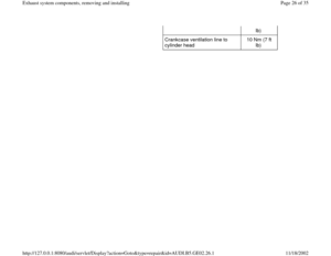
lb)
Crankcase ventilation line to
cylinder head 10 Nm (7 ft
lb)
Pa
ge 26 of 35 Exhaust s
ystem com
ponents, removin
g and installin
g
11/18/2002 htt
p://127.0.0.1:8080/audi/servlet/Dis
play?action=Goto&t
yp
e=re
pair&id=AUDI.B5.GE02.26.1
Page 27 of 35
26-21
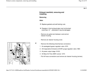
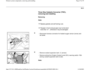
Three Way Catalytic Converter (TWC),
removing and installing
Removing
Note:
Replace gaskets and self-locking nuts.
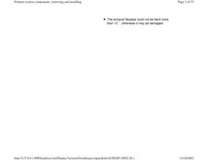
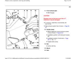
Flexpipe in front exhaust pipe must not be bent
more than 10 , otherwise it may be damaged.
- Disconnect harness connector for heated oxygen sensor (arrow) and
set aside.
Note: - Remove coolant expansion tank -2- (arrows)
- Remove wiring from Engine Coolant Level (ECL) warning switch -F66-
and lay coolant expansion tank to side.
Pa
ge 27 of 35 Exhaust s
ystem com
ponents, removin
g and installin
g
11/18/2002 htt
p://127.0.0.1:8080/audi/servlet/Dis
play?action=Goto&t
yp
e=re
pair&id=AUDI.B5.GE02.26.1
Page 28 of 35
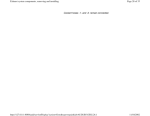
Coolant hoses -1- and -3- remain connected.
Pa
ge 28 of 35 Exhaust s
ystem com
ponents, removin
g and installin
g
11/18/2002 htt
p://127.0.0.1:8080/audi/servlet/Dis
play?action=Goto&t
yp
e=re
pair&id=AUDI.B5.GE02.26.1
Page 29 of 35
26-22
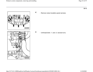
- Remove air guide duct between cowl and air
cleaner housing.
- Remove air cleaner housing cover.
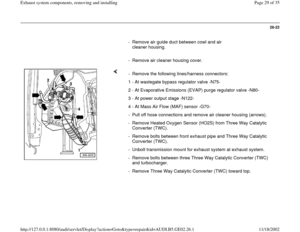
- Remove the following lines/harness connectors:
1 - At wastegate bypass regulator valve -N75-
2 - At Evaporative Emissions (EVAP) purge regulator valve -N80-
3 - At power output stage -N122-
4 - At Mass Air Flow (MAF) sensor -G70-
- Pull off hose connections and remove air cleaner housing (arrows).
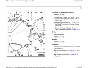
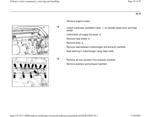
- Remove Heated Oxygen Sensor (HO2S) from Three Way Catalytic
Converter (TWC).
- Remove bolts between front exhaust pipe and Three Way Catalytic
Converter (TWC).
- Unbolt transmission mount for exhaust system at exhaust system.
- Remove bolts between three Three Way Catalytic Converter (TWC)
and turbocharger.
- Remove Three Way Catalytic Converter (TWC) toward top.
Pa
ge 29 of 35 Exhaust s
ystem com
ponents, removin
g and installin
g
11/18/2002 htt
p://127.0.0.1:8080/audi/servlet/Dis
play?action=Goto&t
yp
e=re
pair&id=AUDI.B5.GE02.26.1
Page 30 of 35
26-23
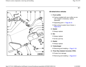
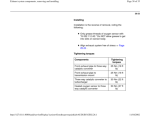
Installing
Installation is the reverse of removal, noting the
following:
Only grease threads of oxygen sensor with
"G 052 112 A3." Do NOT allow grease to get
into slots on sensor body.
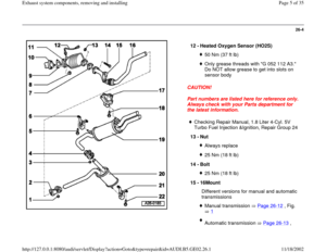
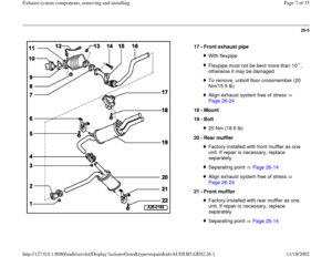
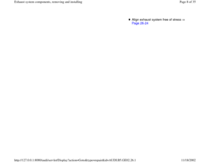
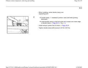
Align exhaust system free of stress Page 26
-24
.
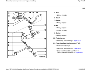
Tightening torques
Components
Tightening
torques
Front exhaust pipe to three way
catalytic converter 25 Nm (18 ft
lb)
Front exhaust pipe to
transmission mount 25 Nm (18 ft
lb)
Three way catalytic converter to
turbocharger 30 Nm (22 ft
lb)
Heated oxygen sensor to three
way catalytic converter 50 Nm (37 ft
lb)
Pa
ge 30 of 35 Exhaust s
ystem com
ponents, removin
g and installin
g
11/18/2002 htt
p://127.0.0.1:8080/audi/servlet/Dis
play?action=Goto&t
yp
e=re
pair&id=AUDI.B5.GE02.26.1
Page 31 of 35
26-24
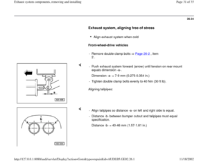
Exhaust system, aligning free of stress
Align exhaust system when cold
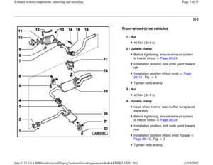
Front-wheel-drive vehicles
- Remove double clamp bolts Page 26
-2 , item
2 .
Aligning tailpipes: - Push exhaust system forward (arrow) until tension on rear mount
equals dimension -a-.
Dimension -a- = 7-9 mm (0.275-0.354 in.)
- Tighten double clamp bolts evenly to 40 Nm (30 ft lb).
- Align tailpipes so distance -a- on left and right side is equal.
- Distance -b- between bumper cutout and tailpipes must equal
specification.
Distance -b- = 40-46 mm (1.57-1.81 in.)
Pa
ge 31 of 35 Exhaust s
ystem com
ponents, removin
g and installin
g
11/18/2002 htt
p://127.0.0.1:8080/audi/servlet/Dis
play?action=Goto&t
yp
e=re
pair&id=AUDI.B5.GE02.26.1
Page 32 of 35
26-25
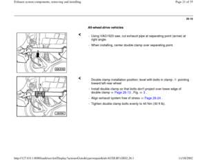
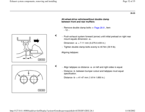
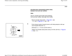
All-wheel-drive vehicleswithout double clamp
between front and rear mufflers
- Remove double clamp bolts Page 26
-9 , item
- 12 -.
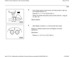
Aligning tailpipes: - Push exhaust system forward (arrow) until initial preload on right rear
mount equals dimension -a-.
Dimension -a- = 7-11 mm (0.275-0.433 in.)
- Tighten double clamp bolts evenly to 40 Nm (30 ft lb).
- Align tailpipes so distance -a- on left and right-sides is equal.
- Distance -b- between bumper cutout and tailpipes must equal
specification.
Distance -b- = 41-47 mm (1.614-1.850 in.)
Pa
ge 32 of 35 Exhaust s
ystem com
ponents, removin
g and installin
g
11/18/2002 htt
p://127.0.0.1:8080/audi/servlet/Dis
play?action=Goto&t
yp
e=re
pair&id=AUDI.B5.GE02.26.1


Crankcase ventilation line to
cylinder head 10 Nm (7 ft
lb)
Pa
ge 26 of 35 Exhaust s
ystem com
ponents, removin
g and installin
g
11/18/2002 htt
p://127.0.0.1:8080/audi/servlet/Dis
play?act")
,
removing and installing
Removing
Note:
Replace gaskets and self-locking nuts.
Flexpipe in front exhaust pipe must not be")


