Page 25 of 47

01-135
Electrical testing, 1997
Note:
Electrical testing, 1996 page 01
-119
.
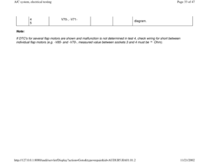
Notes:
VAG1598 test box must not be connected to A/C control head -E87- when performing On Board Diagnostic with VAG1551
Scan Tool (ST)
Further notes, test requirements, connecting adapter cables and test equipment page 01
-115
.
From m.y. 1997, do not connect VAG1598 test box to -E87- for test steps 1.1 through 5.7. (Test box only to be connected
for test steps 5.8, 5.9 and 5.10). Test
number Component(s) tested:
Page
1
- A/C control head -E87-, voltage supply and ground connection
- Signal for time span ignition off Page 01
-
136
2
- Temperature sensors -G17-, G56, -G89- -G191- and -G192- Page 01
-
138
3
- Fresh air blower -V2-, Control module for fresh air blower -J126- Page 01
-
140
4
- Air/temperature distribution flap motors and related potentiometers (-V68-/-G92-, -V70-/-
G112-, -V71-/-G113-, -V85-/-G114-) Page 01
-
141
Pa
ge 25 of 47 A/C s
ystem, electrical testin
g
11/21/2002 htt
p://127.0.0.1:8080/audi/servlet/Dis
play?action=Goto&t
yp
e=re
pair&id=AUDI.B5.HA01.01.2
Page 26 of 47
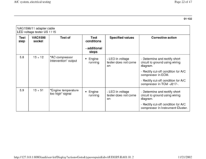
5
- A/C pressure switch -F129-
- "A/C compressor intervention" output
- "Excessive engine temperature" signal
- Interior temperature sensor fan -V42- Page 01
-
142
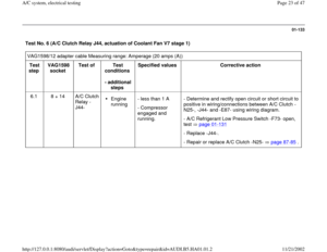
6
- A/C clutch relay -J44-, A/C clutch -N25-, actuation
- Coolant fan -V7-, actuation Page 01
-
146
Pa
ge 26 of 47 A/C s
ystem, electrical testin
g
11/21/2002 htt
p://127.0.0.1:8080/audi/servlet/Dis
play?action=Goto&t
yp
e=re
pair&id=AUDI.B5.HA01.01.2
Page 27 of 47
01-136
Test No. 1 (A/C control head -E87- voltage supply, ground connection) Adapter cable VAG1598/12
Measuring range: Voltage measurement (20 V)
Test
Step VAG1598
socket Test of
Test
conditions
- additional
steps Specified value
Corrective action
1.1 9 + 14 Terminal 15 and ground
connection at -E87-
Ignition on - approx.
battery voltage. - Repair voltage supply or ground
connection using wiring diagram.
1.2 9 + 15 terminal 15 and ground
connection at -E87- Ignition on - approx.
battery voltage. - Repair ground connection using
wiring diagram.
1.3 page 01
-120
1.4 Not for 1997. Terminal 30 no longer connected
1.5 to
1.8 These test steps are conducted only for vehicles up to and including m.y. 1997 (A/C control head with Part. No.
8D0 820 043 and Part No. 8L0 820 043 up to Part No. index letter "C").
Pa
ge 27 of 47 A/C s
ystem, electrical testin
g
11/21/2002 htt
p://127.0.0.1:8080/audi/servlet/Dis
play?action=Goto&t
yp
e=re
pair&id=AUDI.B5.HA01.01.2
Page 28 of 47
01-137
Adapter cable VAG1598/11
LED Voltage tester VAG1527B
Test
Step VAG1598
socket Test of
Test
conditions
- additional
work Specified Value
Corrective action
1.9 term.15 1) +
33 Signal for time
span ignition
off
Ignition
on - LED lights up - Diagnose and repair short or open
circuit in wiring/connections using wiring
diagram.
1.10 term.15 1) +
33 Signal for time
span ignition
off Ignition
on
- Start
engine. - LED lights up
- LED flickers briefly
(time signal) and then
lights up again - Diagnose and repair short or open
circuit in wiring/connections using wiring
diagram.
- Check signal from instrument cluster.
1) Terminal 15 (ignition) is available at -E87- connector -D-, terminal -9-.
Pa
ge 28 of 47 A/C s
ystem, electrical testin
g
11/21/2002 htt
p://127.0.0.1:8080/audi/servlet/Dis
play?action=Goto&t
yp
e=re
pair&id=AUDI.B5.HA01.01.2
Page 29 of 47
01-138
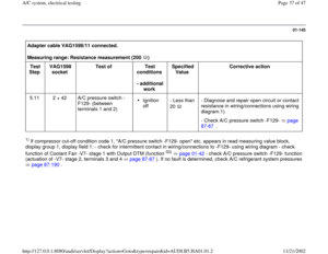
Test No. 2 (Temperature Sensors -G17-, -G56-, -G89-, G191-, G192-. ) Adapter cable VAG1598/11
Measuring range: Resistance measurement (20 K / 200 K ) Test
Step VAG1598
socket Test of
Test conditions
- additional work Specified Value
Corrective action
2.1 to
2.3 page 01
-122
2.4 26 + 49 Sender for outlet
temperature,
center -G191-. - Measure
temperature at
mounting location
of sensor. - Dependant on temperature
at mounting location of
sensor - Diagnose and repair short,
open circuit or contact
resistance in
wiring/connections using
wiring diagram.
2.5 25 + 49 Sender for outlet
temperature, floor
outlet -G192-. - Measure
temperature at
mounting location
of sensor. Confirm using
temperature/resistance
table page 01
-139
- Replace sensor(s)
Pa
ge 29 of 47 A/C s
ystem, electrical testin
g
11/21/2002 htt
p://127.0.0.1:8080/audi/servlet/Dis
play?action=Goto&t
yp
e=re
pair&id=AUDI.B5.HA01.01.2
Page 30 of 47
01-139
Temperature sensor resistances (based on ambient temperature, resistance in k ohm)
Temperature measured at mounting
location of sensor Sender for outlet temperature,
center -G191- Sender for outlet temperature, floor
outlet -G192-
-30 C (-22 F)
(141) (52,7)
-20 C (1 F) (85) (28,6)
-10 C (14 F) (47) 16,2
0C (32F) (29) 9,40
5C (41F) (23,2) 7,27
10 C (50 F) 18,6 5.66
15 C (59 F) 15 4,45
20 C (68 F) 12,2 3,50
25 C (77 F) 10 2,79
30 C (86 F) 8,2 2,23
35 C (95 F) 6,8 1,80
40 C (104 F) 5,7 1,45
50 C (122 F) 4,0 0,97
60 C (140 F) 2,9 0,67
70 C (158 F) 2,1 0,47
Pa
ge 30 of 47 A/C s
ystem, electrical testin
g
11/21/2002 htt
p://127.0.0.1:8080/audi/servlet/Dis
play?action=Goto&t
yp
e=re
pair&id=AUDI.B5.HA01.01.2
Page 31 of 47
01-140
Test No. 3 (Fresh Air Blower -V2- and Control Module for Fresh Air Blower -J126-) Adapter cable VAG1598/11
Measuring range: Voltage measurement (20 V)
Test Step
VAG1598 socket
Test of
Test conditions
- additional work Specified Value
Corrective action
3.1 to 3.3 page 01
-124
Adapter cable VAG1598/11
LED Voltage tester VAG1527B
Test
step VAG1598
socket Test of
Test
conditions
- additional
work Specified
Value Corrective action
3.4 14 + 16 Control module for
fresh air blower -
J126-
Ignition
on - LED lights up - Diagnose and repair open circuit in
wiring between -J126- and -E87- using
wiring diagram.
- Fresh Air Blower -V2- check for ease of
movement.
- Fresh air
blower running. - Replace -J126-.
Pa
ge 31 of 47 A/C s
ystem, electrical testin
g
11/21/2002 htt
p://127.0.0.1:8080/audi/servlet/Dis
play?action=Goto&t
yp
e=re
pair&id=AUDI.B5.HA01.01.2
Page 32 of 47
01-141
Test No. 4 (air/temperature distribution flap motors and related potentiometers) Adapter cable VAG1598/12
Measuring range: Resistance measurement (20 K ) Test
Step VAG1598
socket Test of
Test
conditions
- additional
work Specified
Value Corrective action
4.1 to
4.6 page 01
-126
4.7 14 +
2
3
4
5 Short to ground of wiring to
flap motors -V68-, -V85-, -
V70-, -V71-
Ignition
off - Ohm
- Diagnose and repair short to ground in
wiring/connections using wiring diagram.
Adapter cable VAG1598/12
Measuring range: Voltage measurement (20 V)
Test
Step VAG1598
socket Test of
Test
conditions
- additional
work Specified
Value Corrective action
4.8 14 + 2
3 Short to positive of wiring to
flap motors -V68-, -V85-, -
Ignition
on - less than
1V - Diagnose and repair short to positive
in wiring/connections using wiring
Pa
ge 32 of 47 A/C s
ystem, electrical testin
g
11/21/2002 htt
p://127.0.0.1:8080/audi/servlet/Dis
play?action=Goto&t
yp
e=re
pair&id=AUDI.B5.HA01.01.2


 Adapter cable VAG1598/12
Measuring range: Voltage measurement (20 V)
Test
Step VAG1598
socket Test of
Test
con")
 +")
 Adapter cable VAG1598/11
Measuring range: Resistance measurement (20 K / 200 K ) Test
Step VAG1598
socket Test of")

Temperature measured at mounting
location of sensor Sender for outlet temperature,
center -G191- Sende")
 Adapter cable VAG1598/11
Measuring range: Voltage measurement (20 V)
Test Step
VAG1598 socket
Test of")
 Adapter cable VAG1598/12
Measuring range: Resistance measurement (20 K ) Test
Step VAG1598
socket Test")