Page 1 of 18
01-163
Output Diagnostic Test Mode
(DTM) (scan tool function 03)
Note:
There are two different transmissions:
Transmission with hydraulic controls -E17-, on
which the transmission input speed sensor
(inductive sensor) is secured to the underside
of the valve body.
Transmission with hydraulic regulation -E18/2-,
on which the transmission input speed sensor
(camshaft position sensor) is secured behind
the valve body at the transmission housing.
For information on which transmission is
installed, refer to tables from the following Repair
Manual:
Repair Manual, 5 Spd. Automatic
Transmission 01V, Repair Group 00
Output Diagnostic Test Mode (DTM) for
transmission with hydraulic regulation -E17-
page 01
-164
Output Diagnostic Test Mode (DTM) for
transmission with hydraulic regulation -
Pa
ge 1 of 18 Out
put Dia
gnostic Test Mode
(DTM
) (scan tool function 03
)
11/20/2002 htt
p://127.0.0.1:8080/audi/servlet/Dis
play?action=Goto&t
yp
e=re
pair&id=AUDI.B5.AT02.01.10
Page 2 of 18
E18/2- page 01
-171
Pa
ge 2 of 18 Out
put Dia
gnostic Test Mode
(DTM
) (scan tool function 03
)
11/20/2002 htt
p://127.0.0.1:8080/audi/servlet/Dis
play?action=Goto&t
yp
e=re
pair&id=AUDI.B5.AT02.01.10
Page 3 of 18

(scan tool function 03), transmissions
with hydraulic regulation -E17-
Note:
The Output Diagnostic Test Mode (DTM) can
only be perfor")
01-164
Output Diagnostic Test Mode (DTM)
(scan tool function 03), transmissions
with hydraulic regulation -E17-
Note:
The Output Diagnostic Test Mode (DTM) can
only be performed when the ignition is switched
off, the selector lever is in position "P", the
engine is not running, and the vehicle is
stationary.
DTM will be terminated when the engine is
started.
The function of solenoid valves 1 -N88-, 2 -N89-
, 3 -N90- and the solenoids for the selector
lever lock are checked acoustically during the
DTM. Avoid noise in the surrounding area
during the acoustic check, because the
switching noise (clicking) of the actuators is
very quiet.
The solenoid valves 4 -N91-, 5 -N92-, 6 -N93-
and 7 -N94- are activated during the DTM. A
direct functional check of these valves is not
possible. But possible electrical faults which
occur during the activation, will be recognized
by the On Board Diagnostic (OBD) and stored
in the DTC memory.
Pa
ge 3 of 18 Out
put Dia
gnostic Test Mode
(DTM
) (scan tool function 03
)
11/20/2002 htt
p://127.0.0.1:8080/audi/servlet/Dis
play?action=Goto&t
yp
e=re
pair&id=AUDI.B5.AT02.01.10
Page 4 of 18
01-165
When performing the Output Diagnostic Test
Mode (DTM), the individual actuators will be
activated until the button is pressed.
Only one complete DTM is possible after
switching the ignition on. To repeat DTM, the
ignition must be switched off and on again.
Activation sequence
1. Solenoid Valve 1 -N88-
2. Solenoid Valve 2 -N89-
3. Solenoid Valve 3 -N90-
4. Shift Lock solenoid -N110-
5. Solenoid Valve 4 -N91-
6. Solenoid Valve 5 -N92-
7. Solenoid Valve 6 -N93-
8. Solenoid Valve 7 -N94-
9. Kick-down Switch -F8-
(Kick-down for air conditioner)
10. Solenoid Valve Relay
Pa
ge 4 of 18 Out
put Dia
gnostic Test Mode
(DTM
) (scan tool function 03
)
11/20/2002 htt
p://127.0.0.1:8080/audi/servlet/Dis
play?action=Goto&t
yp
e=re
pair&id=AUDI.B5.AT02.01.10
Page 5 of 18
01-166
Test sequence
- Connect VAS 5051 tester or V.A.G 1551 scan
tool and enter address word 02 for "Control
module for Transmission electronics" page
01
-40
.
Ignition must be switched off during this
process. Rapid data transfer
HELP
Select function XX
Indicated on display:
- Press keys 0 and 3. (03 selects the function "Output Diagnostic Test
Mode").
Rapid data transfer
Q
03 - Output Dia
gnostic Test Mode
Indicated on display
- Press Q- button to confirm entry.
Output Diagnostic Test Mode
-
Solenoid valve 1 -N88
Indicated on display
-
Valve is activated (clicks). To switch to next actuator press key.- If valve does not click, perform electrical check Page 01
-273
.
Malfunction is stored in DTC memory, see DTC table Page 01
-45
.
Pa
ge 5 of 18 Out
put Dia
gnostic Test Mode
(DTM
) (scan tool function 03
)
11/20/2002 htt
p://127.0.0.1:8080/audi/servlet/Dis
play?action=Goto&t
yp
e=re
pair&id=AUDI.B5.AT02.01.10
Page 6 of 18
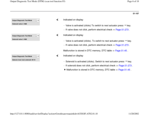
01-167
Output Diagnostic Test Mode
-
Solenoid valve 2 -N89
Indicated on display
-
Valve is activated (clicks) To switch to next actuator press key.- If valve does not click, perform electrical check Page 01
-273
.
Output Diagnostic Test Mode
-
Solenoid valve 3 -N90
Indicated on display
Malfunction is stored in DTC memory, DTC table Page 01
-45
. -
Valve is activated (clicks). To switch to next actuator press key.
- If valve does not click, perform electrical check Page 01
-273
.
Output Diagnostic Test Mode
-
Selector lever lock solenoid -N110
Indicated on display
-
Solenoid is activated (clicks). Switch to next actuator press key.- If solenoid does not click, perform electrical check Page 01
-273
.
Malfunction is stored in DTC memory, DTC table Page 01
-45
.
Pa
ge 6 of 18 Out
put Dia
gnostic Test Mode
(DTM
) (scan tool function 03
)
11/20/2002 htt
p://127.0.0.1:8080/audi/servlet/Dis
play?action=Goto&t
yp
e=re
pair&id=AUDI.B5.AT02.01.10
Page 7 of 18
01-168
Output Diagnostic Test Mode
-
Solenoid valve 4 -N91
Indicated on display
Electrical malfunctions will be stored in DTC memory. See DTC table
Page 01
-45
. -
Valve is activated (clicks). To switch to next actuator press key.
Output Diagnostic Test Mode
-
Solenoid valve 5 -N92
Indicated on display
Electrical malfunctions will be stored in DTC memory. See DTC table
Page 01
-45
. -
Valve is activated (clicks). To switch to next actuator press key.
Output Diagnostic Test Mode
-
Solenoid valve 6 -N93
Indicated on display
Electrical malfunctions will be stored in DTC memory. See DTC table
Page 01
-45
. -
Valve is activated (clicks). Switch to the next actuator press key.
Pa
ge 7 of 18 Out
put Dia
gnostic Test Mode
(DTM
) (scan tool function 03
)
11/20/2002 htt
p://127.0.0.1:8080/audi/servlet/Dis
play?action=Goto&t
yp
e=re
pair&id=AUDI.B5.AT02.01.10
Page 8 of 18

01-169
Output Diagnostic Test Mode
-
Solenoid valve 7 -N94
Indicated on display
Electrical malfunctions will be stored in DTC memory. See DTC table
Page 01
-45
. -
Valve is activated (clicks). To switch to next actuator press key.
Output Diagnostic Test Mode
-
Kick-down switch -F8
Indicated on display
Notes:
It is not the kick-down switch -F8-, but the switch-off function for the air
conditioner in transmission control module -J217- which is activated. If the kick-down switch is operated, the Transmission Control Module
(TCM) grounds the output to air conditioner. This briefly switches off
the air conditioner compressor. Can be disregarded here. The signal can be checked in measured value block 011 01
-186
.
For checking function of Kick-down switch -F8- Page 01
-273
Electrical check.
-
Press key to switch to the next actuator.
Pa
ge 8 of 18 Out
put Dia
gnostic Test Mode
(DTM
) (scan tool function 03
)
11/20/2002 htt
p://127.0.0.1:8080/audi/servlet/Dis
play?action=Goto&t
yp
e=re
pair&id=AUDI.B5.AT02.01.10


 (scan tool function 03)
Note:
There are two different transmissions:
Transmission with hydraulic controls -E17-, on
which the tr")
 (scan tool function 03
)
11/20/2002 htt
p://127.0.0.1:8080/audi/servlet/Dis
play?action=Goto&t
yp
e=re
pair&id=AUDI.B5.AT02")
, the individual actuators will be
activated until the button is pressed.
Only one complete DTM is possible after
switchi")

 To switch to next actuator press key.- If valve does not click, perform ele")
