Page 661 of 1202
ST0MW-01
B05050
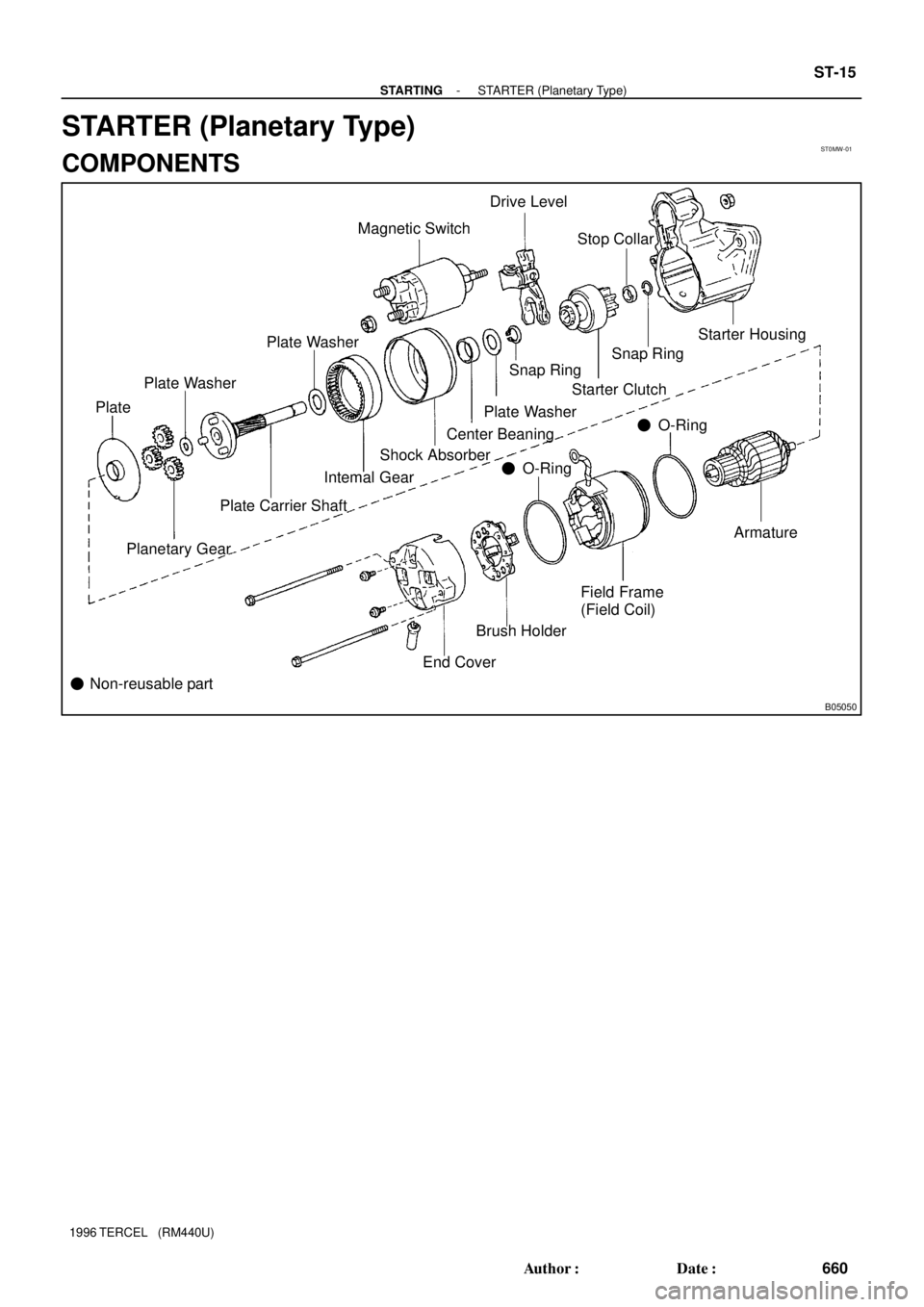
Magnetic Switch
Drive Level
Plate Washer
PlateStop Collar
Starter Housing
Snap Ring
Starter Clutch
Planetary GearPlate Carrier ShaftIntemal Gear
� Non-reusable partSnap Ring
Plate Washer
Center Beaning
Armature Plate Washer
� O-Ring Shock Absorber
Field Frame
(Field Coil)
End CoverBrush Holder� O-Ring
- STARTINGSTARTER (Planetary Type)
ST-15
660 Author�: Date�:
1996 TERCEL (RM440U)
STARTER (Planetary Type)
COMPONENTS
Page 715 of 1202
MX07D-03
MX-2
- MANUAL TRANSAXLETROUBLESHOOTING
714 Author�: Date�:
1996 TERCEL (RM440U)
TROUBLESHOOTING
PROBLEM SYMPTOMS TABLE
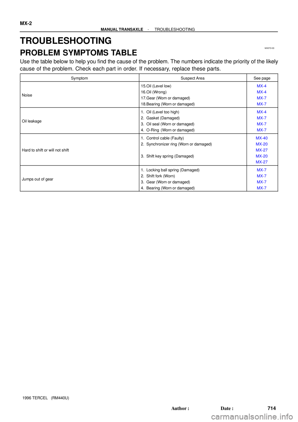
Use the table below to help you find the cause of the problem. The numbers indicate the priority of the likely
cause of the problem. Check each part in order. If necessary, replace these parts.
SymptomSuspect AreaSee page
Noise
15.Oil (Level low)
16.Oil (Wrong)
17.Gear (Worn or damaged)
18.Bearing (Worn or damaged)MX-4
MX-4
MX-7
MX-7
Oil leakage
1. Oil (Level too high)
2. Gasket (Damaged)
3. Oil seal (Worn or damaged)
4. O-Ring (Worn or damaged)MX-4
MX-7
MX-7
MX-7
Hard to shift or will not shift
1. Control cable (Faulty)
2. Synchronizer ring (Worn or damaged)
3. Shift key spring (Damaged)MX-40
MX-20
MX-27
MX-20
MX-27
Jumps out of gear
1. Locking ball spring (Damaged)
2. Shift fork (Worn)
3. Gear (Worn or damaged)
4. Bearing (Worn or damaged)MX-7
MX-7
MX-7
MX-7
Page 717 of 1202
MX07F-04
Q06439
Z1891017 mm Head
Starter Set Bolt
Q06443
Q09187
Filler Plug
Oil Level
0 - 5 mm
Drain Plug MX-4
- MANUAL TRANSAXLEMANUAL TRANSAXLE UNIT
1996 TERCEL (RM440U)
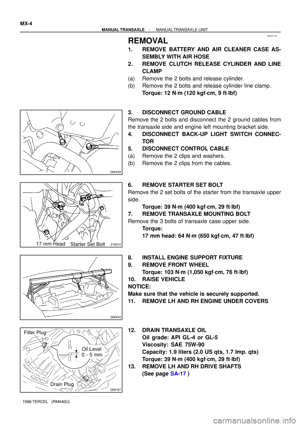
REMOVAL
1. REMOVE BATTERY AND AIR CLEANER CASE AS-
SEMBLY WITH AIR HOSE
2. REMOVE CLUTCH RELEASE CYLINDER AND LINE
CLAMP
(a) Remove the 2 bolts and release cylinder.
(b) Remove the 2 bolts and release cylinder line clamp.
Torque: 12 N´m (120 kgf´cm, 9 ft´lbf)
3. DISCONNECT GROUND CABLE
Remove the 2 bolts and disconnect the 2 ground cables from
the transaxle side and engine left mounting bracket side.
4. DISCONNECT BACK-UP LIGHT SWITCH CONNEC-
TOR
5. DISCONNECT CONTROL CABLE
(a) Remove the 2 clips and washers.
(b) Remove the 2 clips from the cables.
6. REMOVE STARTER SET BOLT
Remove the 2 set bolts of the starter from the transaxle upper
side.
Torque: 39 N´m (400 kgf´cm, 29 ft´lbf)
7. REMOVE TRANSAXLE MOUNTING BOLT
Remove the 3 bolts of transaxle case upper side.
Torque:
17 mm head: 64 N´m (650 kgf´cm, 47 ft´lbf)
8. INSTALL ENGINE SUPPORT FIXTURE
9. REMOVE FRONT WHEEL
Torque: 103 N´m (1,050 kgf´cm, 76 ft´lbf)
10. RAISE VEHICLE
NOTICE:
Make sure that the vehicle is securely supported.
11. REMOVE LH AND RH ENGINE UNDER COVERS
12. DRAIN TRANSAXLE OIL
Oil grade: API GL-4 or GL-5
Viscosity: SAE 75W-90
Capacity: 1.9 liters (2.0 US qts, 1.7 Imp. qts)
Torque: 39 N´m (400 kgf´cm, 29 ft´lbf)
13. REMOVE LH AND RH DRIVE SHAFTS
(See page SA-17)
Page 773 of 1202
AX0RQ-01
D01628
SST
SST LH Side
RH Side
AX-20
- AUTOMATIC TRANSAXLE (A132L)DIFFERENTIAL OIL SEAL
1996 TERCEL (RM440U)
INSTALLATION
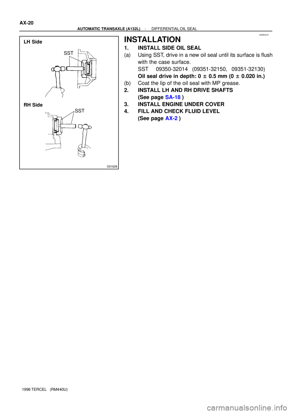
1. INSTALL SIDE OIL SEAL
(a) Using SST, drive in a new oil seal until its surface is flush
with the case surface.
SST 09350-32014 (09351-32150, 09351-32130)
Oil seal drive in depth: 0 ± 0.5 mm (0 ± 0.020 in.)
(b) Coat the lip of the oil seal with MP grease.
2. INSTALL LH AND RH DRIVE SHAFTS
(See page SA-18)
3. INSTALL ENGINE UNDER COVER
4. FILL AND CHECK FLUID LEVEL
(See page AX-2)
Page 807 of 1202
AX0S4-01
D01627
SST
SST LH Side
RH Side
AX-24
- AUTOMATIC TRANSAXLE (A242L)DIFFERENTIAL OIL SEAL
1996 TERCEL (RM440U)
INSTALLATION
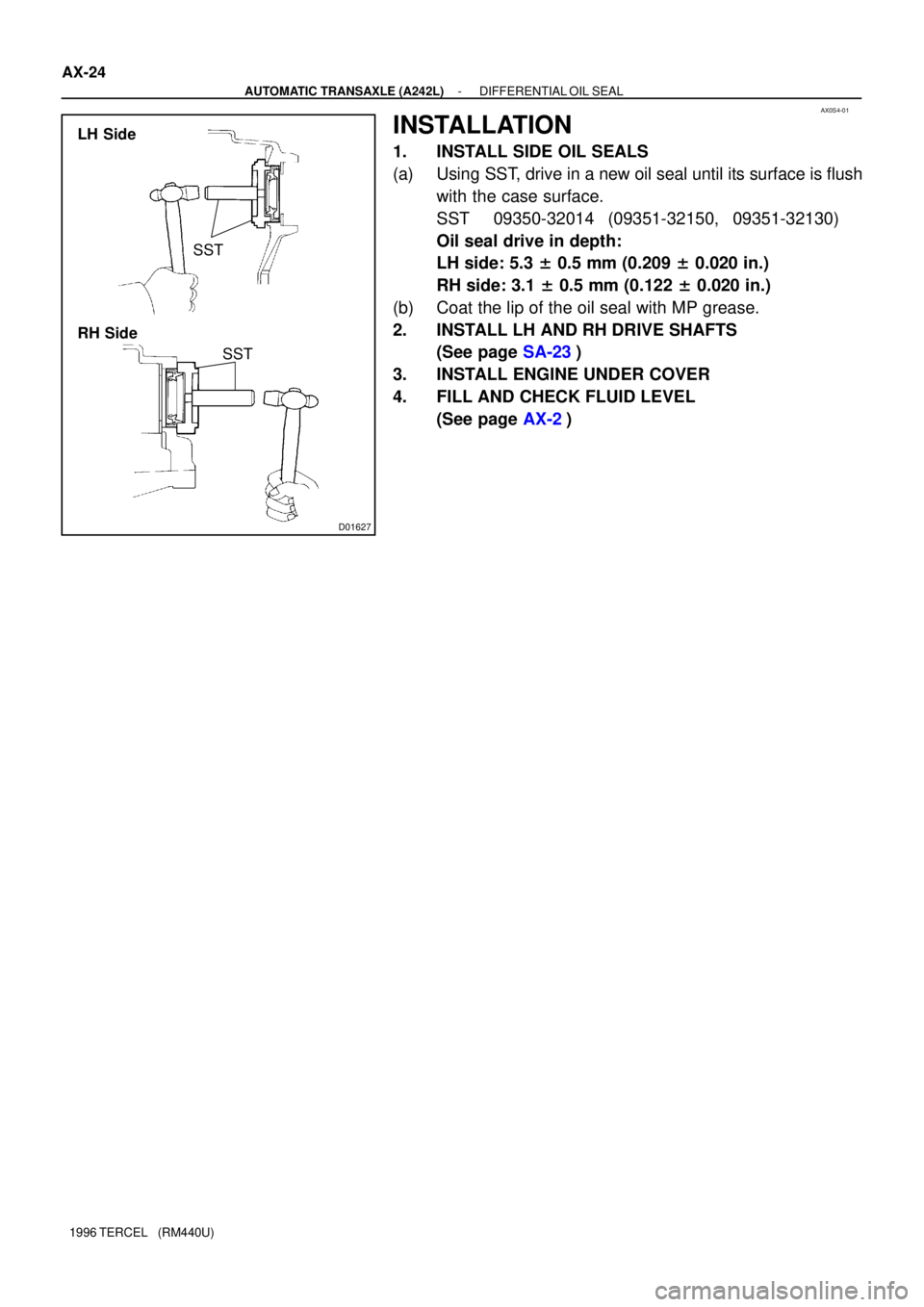
1. INSTALL SIDE OIL SEALS
(a) Using SST, drive in a new oil seal until its surface is flush
with the case surface.
SST 09350-32014 (09351-32150, 09351-32130)
Oil seal drive in depth:
LH side: 5.3 ± 0.5 mm (0.209 ± 0.020 in.)
RH side: 3.1 ± 0.5 mm (0.122 ± 0.020 in.)
(b) Coat the lip of the oil seal with MP grease.
2. INSTALL LH AND RH DRIVE SHAFTS
(See page SA-23)
3. INSTALL ENGINE UNDER COVER
4. FILL AND CHECK FLUID LEVEL
(See page AX-2)
Page 875 of 1202
N00746
BR-22
- BRAKEFRONT BRAKE PAD
1996 TERCEL (RM440U)
(e) Install inner pad with the pad wear indicator plate facing
upward.
(f) Install outer pad.
NOTICE:
There should be no oil or grease adhering to the friction
surfaces of the pads or the disc.
8. INSTALL CALIPER
(a) Draw out a small amount of brake fluid from the reservoir.
(b) Press in the piston with a hammer handle or an equiva-
lent.
HINT:
If the piston is difficult to push in, loosen the bleeder plug and
push in the piston while letting some brake fluid escape.
(c) Install the caliper.
(d) Install and torque the 2 installation bolts.
Torque: 25 N´m (255 kgf´cm, 18 ft´lbf)
9. INSTALL FRONT WHEEL
10. CHECK THAT FLUID LEVEL IS AT MAX LINE
Page 905 of 1202
SR05Q-17
R11229
NormalAbnormal
R11025Engine Idling Engine Stopped5 mm (0.20 in.)
or less SR-6
- STEERINGPOWER STEERING FLUID
1996 TERCEL (RM440U)
INSPECTION
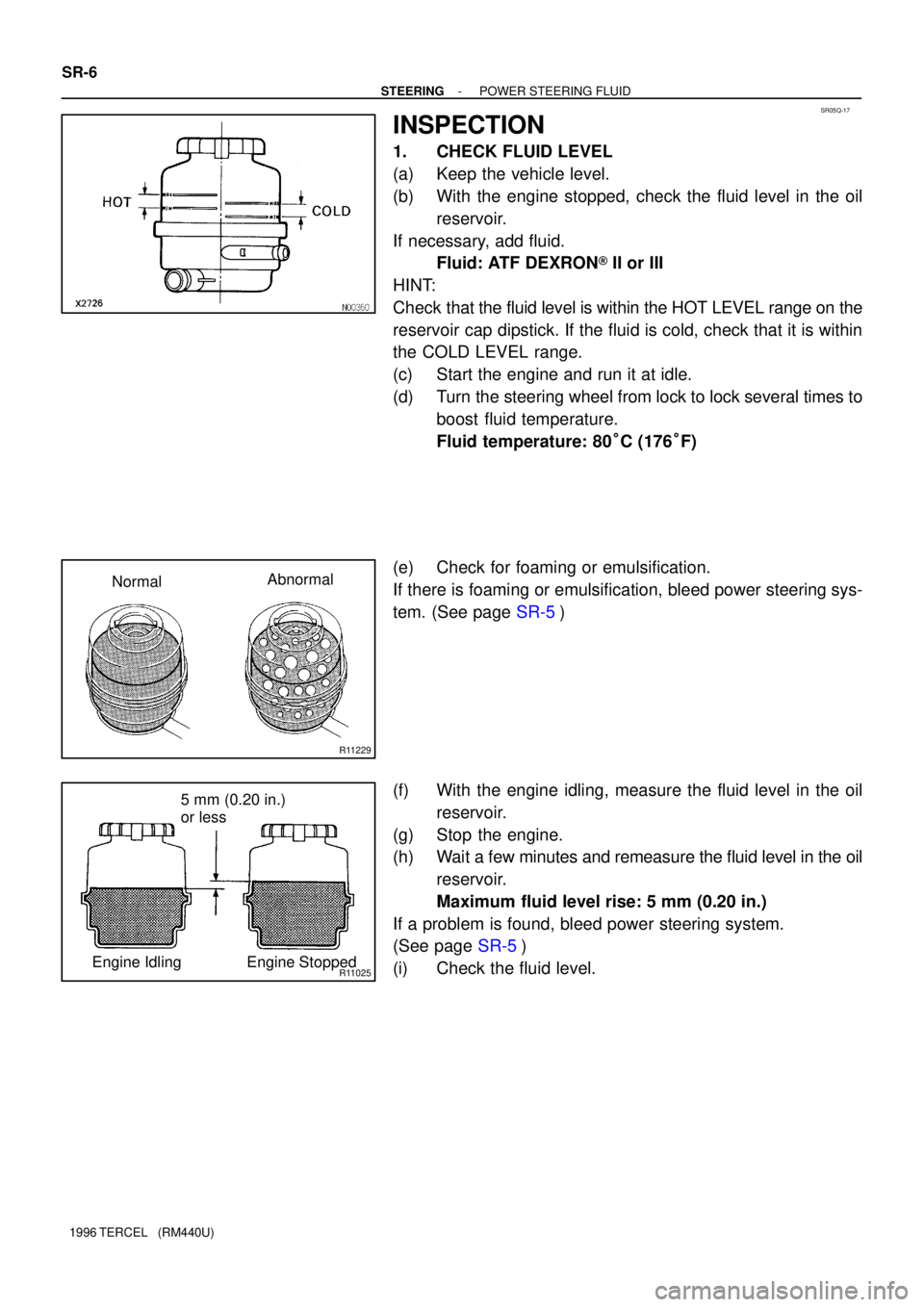
1. CHECK FLUID LEVEL
(a) Keep the vehicle level.
(b) With the engine stopped, check the fluid level in the oil
reservoir.
If necessary, add fluid.
Fluid: ATF DEXRON® II or III
HINT:
Check that the fluid level is within the HOT LEVEL range on the
reservoir cap dipstick. If the fluid is cold, check that it is within
the COLD LEVEL range.
(c) Start the engine and run it at idle.
(d) Turn the steering wheel from lock to lock several times to
boost fluid temperature.
Fluid temperature: 80°C (176°F)
(e) Check for foaming or emulsification.
If there is foaming or emulsification, bleed power steering sys-
tem. (See page SR-5)
(f) With the engine idling, measure the fluid level in the oil
reservoir.
(g) Stop the engine.
(h) Wait a few minutes and remeasure the fluid level in the oil
reservoir.
Maximum fluid level rise: 5 mm (0.20 in.)
If a problem is found, bleed power steering system.
(See page SR-5)
(i) Check the fluid level.
Page 1008 of 1202
- BODY ELECTRICALBODY ELECTRICAL SYSTEM
BE-7
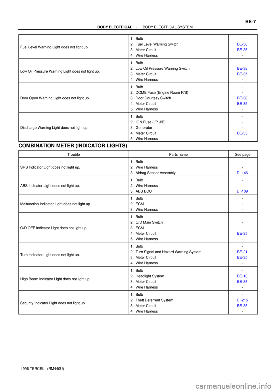
1996 TERCEL (RM440U) Fuel Level Warning Light does not light up.
1. Bulb
2. Fuel Level Warning Switch
3. Meter Circuit
4. Wire Harness-
BE-38
BE-35
-
Low Oil Pressure Warning Light does not light up.
1. Bulb
2. Low Oil Pressure Warning Switch
3. Meter Circuit
4. Wire Harness-
BE-38
BE-35
-
Door Open Warning Light does not light up.
1. Bulb
2. DOME Fuse (Engine Room R/B)
3. Door Courtesy Switch
4. Meter Circuit
5. Wire Harness-
-
BE-38
BE-35
-
Discharge Warning Light does not light up.
1. Bulb
2. IGN Fuse (I/P J/B)
3. Generator
4. Meter Circuit
5. Wire Harness-
-
-
BE-35
-
COMBINATION METER (INDICATOR LIGHTS)
TroubleParts nameSee page
SRS Indicator Light does not light up.
1. Bulb
2. Wire Harness
3. Airbag Sensor Assembly-
-
DI-146
ABS Indicator Light does not light up.
1. Bulb
2. Wire Harness
3. ABS ECU-
-
DI-109
Malfunction Indicator Light does not light up.
1. Bulb
2. ECM
3. Wire Harness-
-
-
O/D OFF Indicator Light does not light up.
1. Bulb
2. O/D Main Switch
3. ECM
4. Meter Circuit
5. Wire Harness-
-
-
BE-35
-
Turn Indicator Light does not light up.
1. Bulb
2. Turn Signal and Hazard Warning System
3. Meter Circuit
4. Wire Harness-
BE-21
BE-35
-
High Beam Indicator Light does not light up.
1. Bulb
2. Headlight System
3. Meter Circuit
4. Wire Harness-
BE-13
BE-35
-
Security Indicator Light does not light up.
1. Bulb
2. Theft Deterrent System
3. Meter Circuit
4. Wire Harness-
DI-215
BE-35
-