Page 549 of 2062

Downloaded from www.Manualslib.com manuals search engine − DIAGNOSTICSAUTOMATIC TRANSMISSION
DI−285
1996 TOYOTA T100 (RM449U)
Chapter 3: Off−Vehicle Repair Matrix Chart
(�: A340E, A340F, A340H AUTOMATIC TRANSMISSION Repair Manual Pub. No. RM391U)
(�: A340F, A343F AUTOMATIC TRANSMISSION Repair Manual Pub. No. RM479U)
SymptomSuspect AreaSee page
Vehicle does not move in any forward position and reverse posi-
tion
1. O/D one−way clutch (F0)
2. O/D direct clutch (C
0)
3. O/D planetary gear unit
4. Torque converter clutch
�
�
�
AT−38
Vehicle does not move in R position
1. Front and rear planetary gear unit
2. Direct clutch (C
2)
3. 1st and reverse brake (B
3)
4. O/D direct clutch (C
0)
�
�
�
�
No up−shift (1st → 2nd)1. 2nd brake (B2)
2. No. 1 one−way clutch (F
1)
�
�
No up−shift (2nd → 3rd)1. Direct clutch (C2)�
No up−shift (3rd → O/D)1. O/D brake (B0)�
No lock−up or No lock−up off1. Torque converter clutchAT−38
Harsh engagement (N → D)
1. Forward clutch (C1)
2. O/D one−way clutch (F
0)
3. No. 2 one−way clutch (F
2)
�
�
�
Harsh engagement (N → R)
1. Direct clutch (C2)
2. 1st and reverse brake (B
3)
3. O/D one−way clutch (F
0)
�
�
�
Harsh engagement (N → 2)
1. Forward clutch (C1)
2. O/D one−way clutch (F
0)
3. No. 2 one−way clutch (F
2)
�
�
�
Harsh engagement (N → L)
1. Forward clutch (C1)
2. 1st and reverse brake (B
3)
3. O/D one−way clutch (F
0)
4. No. 2 one−way clutch (F
2)
�
�
�
�
Harsh engagement (Lock−up)1. Torque converter clutchAT−38
Slip or shudder (Forward and reverse: After warm−up)
1. Torque converter clutch
2. O/D one−way clutch (F
0)
3. O/D direct clutch (C
0)
AT−38
�
�
Slip or shudder (Particular position: Just after engine starts)1. Torque converter clutchAT−38
Slip or shudder (R position)1. Direct clutch (C2)
2. 1st and reverse brake (B
3)
�
�
Slip or shudder (1st)1. Forward clutch (C1)
2. No. 2 one−way clutch (F
2)
�
�
Slip or shudder (2nd)
1. 2nd brake (B2)
2. 2nd coast brake (B
1)
3. No. 1 one−way clutch (F
1)
�
�
�
Slip or shudder (3rd)1. Direct clutch (C2)�
Slip or shudder (O/D)1. O/D brake (B0)�
No engine braking (1st ∼ 3rd: D position)1. 2nd brake (B2)�
No engine braking (1st: L position)1. 1st and reverse brake (B3)�
No engine braking (2nd: 2 position)1. 2nd coast brake (B1)�
Poor acceleration (All position)1. Torque converter clutchAT−38
Poor acceleration (O/D)1. O/D direct clutch (C0)
2. O/D planetary gear unit�
�
Engine stalls when starting off or stopping1. Torque converter clutchAT−38
Page 558 of 2062

Downloaded from www.Manualslib.com manuals search engine Q06995
Drain
Line
Pressure
Q07640
DI−294
− DIAGNOSTICSAUTOMATIC TRANSMISSION
1996 TOYOTA T100 (RM449U)
DTC P0770 Shift Solenoid E Malfunction
(Shift Solenoid Valve SL)
SYSTEM DESCRIPTION
The ECM uses the signals from the Throttle position sensor,
mass air flow meter and crankshaft position sensor to monitor
the engagement condition of the lock−up clutch.
Then the ECM compares the engagement condition of the
lock−up clutch with the lock−up schedule in the ECM memory
to detect mechanical trouble of the shift solenoid valve SL,
valve body and torque converter clutch.
DTC No.DTC Detecting ConditionTrouble Area
P0770
Lock−up does not occur when driving in the lock−up range
(normal driving at 80 km/h [50 mph]), or lock−up remains ON
in the lock−up OFF range
(2 trip detection logic)�Shift solenoid valve SL is stuck open or closed
�Valve body blocked up or stuck
�Lock−up clutch
INSPECTION PROCEDURE
1 Check solenoid valve SL operation.
PREPARATION:
(a) Remove the oil pan.
(b) Remove the shift solenoid valve SL.
CHECK:
(a) Applying 490 kPa (5 kgf/cm2, 71 psi) of compressed air,
check that the solenoid valve does not leak air.
(b) When battery voltage is supplied to the shift solenoid
valve, check that the solenoid valve opens.
NG Replace solenoid valve SL.
OK
DI0VR−01
Page 559 of 2062
Downloaded from www.Manualslib.com manuals search engine − DIAGNOSTICSAUTOMATIC TRANSMISSION
DI−295
1996 TOYOTA T100 (RM449U)
2 Check valve body (See page DI−282).
NG Repair or replace valve body.
OK
Replace torque converter clutch
(See page AT−26, AT−33).
Page 560 of 2062

Downloaded from www.Manualslib.com manuals search engine Q07379
Transmission
Shift Solenoid
Valve SL
Y
E23
Y−BB+
SL 27 8
E7
E7
*1 *2
*1: 3RZ−FE
*2: 5VZ−FEECM DI−296
− DIAGNOSTICSAUTOMATIC TRANSMISSION
1996 TOYOTA T100 (RM449U)
DTC P0773 Shift Solenoid E Electrical Malfunction
(Shift Solenoid Valve SL)
CIRCUIT DESCRIPTION
The shift solenoid valve SL is turned ON and OFF by signals from the ECM to control the hydraulic pressure
acting on the lock−up relay valve, which then controls operation of the lock−up clutch.
Fail safe function:
If the ECM detects a malfunction, it turns the shift solenoid valve SL OFF.
DTC No.Detection ItemDTC Detecting ConditionTrouble Area
P0773
Either (a) or (b) are detected for 1 time:
(2 trip detection logic)
(a) Solenoid resistance is 8 Ω or less (short circuit) when sole-
noid is energized
(b) Solenoid resistance is 100 kΩ or more (open circuit) when
solenoid is not energized
�Open or short in shift solenoid valve SL circuit
�Shift solenoid valve SL
�ECM
WIRING DIAGRAM
DI0VU−01
Page 567 of 2062
Downloaded from www.Manualslib.com manuals search engine Q06437Q06436D00222No.2 Vehicle Speed SensorSensor Rotor
Reed Switch
”ON”
Permanent Magnet
D00251
GND2 V/div.
10 msec. /division
− DIAGNOSTICSAUTOMATIC TRANSMISSION
DI−303
1996 TOYOTA T100 (RM449U)
DTC P1700 Speed Sensor No.2 Circuit Malfunction
(No.2 Vehicle Speed Sensor) (5VZ−FE)
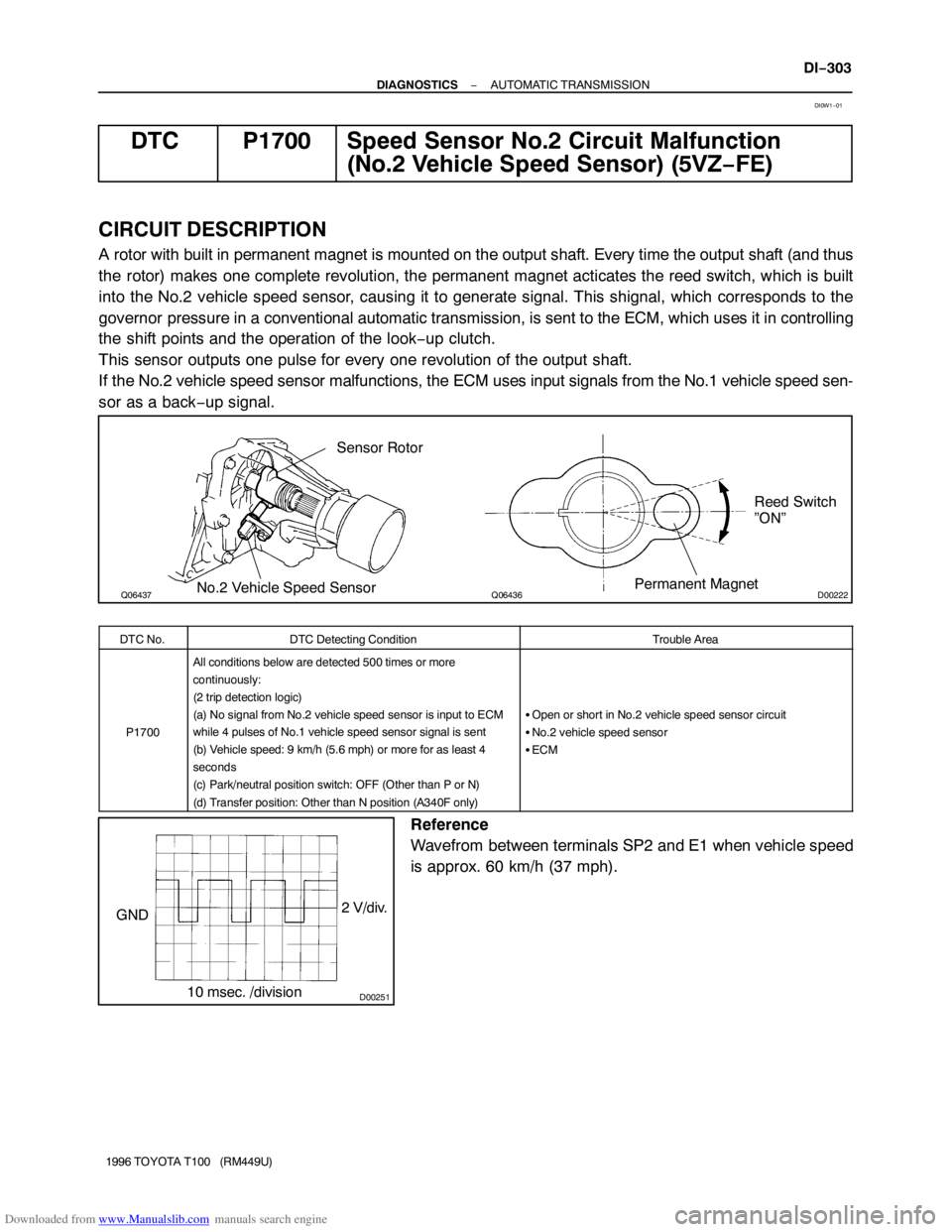
CIRCUIT DESCRIPTION
A rotor with built in permanent magnet is mounted on the output shaft. Every time the output shaft (and thus
the rotor) makes one complete revolution, the permanent magnet acticates the reed switch, which is built
into the No.2 vehicle speed sensor, causing it to generate signal. This shignal, which corresponds to the
governor pressure in a conventional automatic transmission, is sent to the ECM, which uses it in controlling
the shift points and the operation of the look−up clutch.
This sensor outputs one pulse for every one revolution of the output shaft.
If the No.2 vehicle speed sensor malfunctions, the ECM uses input signals from the No.1 vehicle speed sen-
sor as a back−up signal.
DTC No.DTC Detecting ConditionTrouble Area
P1700
All conditions below are detected 500 times or more
continuously:
(2 trip detection logic)
(a) No signal from No.2 vehicle speed sensor is input to ECM
while 4 pulses of No.1 vehicle speed sensor signal is sent
(b) Vehicle speed: 9 km/h (5.6 mph) or more for as least 4
seconds
(c) Park/neutral position switch: OFF (Other than P or N)
(d) Transfer position: Other than N position (A340F only)
�Open or short in No.2 vehicle speed sensor circuit
�No.2 vehicle speed sensor
�ECM
Reference
Wavefrom between terminals SP2 and E1 when vehicle speed
is approx. 60 km/h (37 mph).
DI0W1−01
Page 580 of 2062
Downloaded from www.Manualslib.com manuals search engine D09979
DI−316
− DIAGNOSTICSAUTOMATIC TRANSMISSION
1996 TOYOTA T100 (RM449U)
Stop Light Switch Circuit
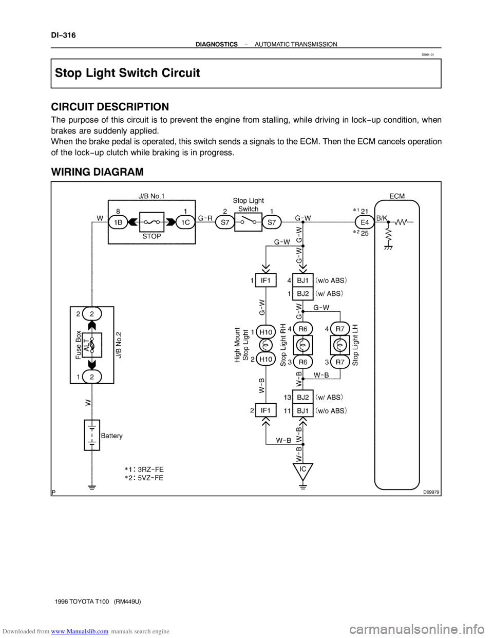
CIRCUIT DESCRIPTION
The purpose of this circuit is to prevent the engine from stalling, while driving in lock−up condition, when
brakes are suddenly applied.
When the brake pedal is operated, this switch sends a signals to the ECM. Then the ECM cancels operation
of the lock−up clutch while braking is in progress.
WIRING DIAGRAM
DI98I−01
Page 678 of 2062

Downloaded from www.Manualslib.com manuals search engine BE6443
1
12
No.Operation MethodCRUISE MAIN Indicator LIght
Blinking PatternDiagnosis
1
2
3
4Drive approx. 40 km/h
(25 mph) or over
Drive approx 40 km/h
(25 mph) or below
LightON
OFF
LightON
OFF
ON
OFFSET/COAST switch circuit
is normal
RES/ACC switch circuit
is normal
LightON
OFF LightON
OFF
1sec.
0.25 sec. 0.25 sec.Push the speed control switch
SET/COAT on.
Push the speed control switch
RESUME/ACCEL on.
Each cancel switch turned
ON.
� Speed control switch (to
CANCEL)
� Stop light switch
� Park/Neutral position switch
(to N or O Position)
� Clutch start switch
� Parking brake switch
Speed sensor circuit is
normal
Speed sensor circuit is
normalEach cancel switch is
normal
5 DI−414
− DIAGNOSTICSCRUISE CONTROL SYSTEM
1996 TOYOTA T100 (RM449U)
5. INPUT SIGNAL CHECK
HINT:
�For check No.1 ∼ No.3
Turn ignition switch ON.
�For check No.4
Jack up the vehicle.
Start the engine.
Shift to D position.
(a) Press the control switch to SET/COAST or RES/ACC
position and hold it down or hold it up ”(1)”.
(b) Push the main switch ON ”(2)”.
(c) Check that the CRUISE MAIN indicator light blinks twice
or 3 times repeatedly after 3 seconds.
(d) Turn the SET/COAST or RES/ACC switch OFF.
(e) Operate each switch as listed in the table below.
(f) Read the blinking pattern of the CRUISE MAIN indicator
light.
(g) After performing the check, turn the main switch OFF.
HINT:
When 2 or more signals are input to the ECU, the lowest num-
bered code will be displayed first.
Page 679 of 2062

Downloaded from www.Manualslib.com manuals search engine DI34W−02
− DIAGNOSTICSCRUISE CONTROL SYSTEM
DI−415
1996 TOYOTA T100 (RM449U)
DIAGNOSTIC TROUBLE CODE CHART
If a malfunction code is displayed during the DTC check, check the circuit listed for that code in the table
below and proceed to the appropriate page.
DTC No.
(See Page)Detection ItemTrouble Area
11
(DI−420)�Actuator Motor Circuit
�Actuator
�Wire harness
�Cruise control ECU
12
(DI−422)�Actuator Magnetic Clutch Circuit
�Actuator
�Stop light switch
�Wire harness
�Cruise control ECU
13
(DI−425)�Actuator Position Sensor Circuit
�Actuator
�Wire harness
�Cruise control ECU
21
(DI−428)�Vehicle Speed Sensor Circuit
�Vehicle speed sensor
�Wire harness
�Cruise control ECU
*23
(DI−428)�Actuator Control Cable
�Vehicle Speed Sensor circuit
�Vehicle speed sensor
�Speed control cable function
�Wire harness
�Cruise control ECU
32
(DI−431)�Control Switch Circuit
�Cruise control switch
�Wire harness
�Cruise control ECU
34
(DI−431)�Voltage abnormality in control switch circuit
�Control switch
�Wire harness
�Cruise control ECU
41� Cruise Control ECU�Cruise control ECU
HINT:
When 2 or more codes are indicated, the lowest numbered code will be displayed first.
*When the vehicle speed decreases on uphill roads, the speed can be set again and drive can be continued
(This is not a malfunction.).