Page 1072 of 2062
Downloaded from www.Manualslib.com manuals search engine Z02917
Ohmmeter
Acceptable
TEMPERATURE °C (°F)
RESISTANCE kΩ
− SFI (5VZ−FE)ENGINE COOLANT TEMPERATURE (ECT) SENSOR
SF−53
1996 TOYOTA T100 (RM449U)
6. INSPECT ECT SENSOR
Using an ohmmeter, measure the resistance between the ter-
minals.
Resistance:
Refer to the graph
If the resistance is not as specified, replace the ECT sensor.
7. REINSTALL ECT SENSOR
(a) Install a new gasket to the ECT sensor.
(b) Using a 19 mm deep socket, install the ECT sensor.
Torque: 20 N·m (200 kgf·cm, 14 ft·lbf)
(c) Connect the ECT sensor connector.
8. REINSTALL FUEL PIPE
Install the fuel pipe with 4 new gaskets and the 2 union bolts.
Torque: 34.3 N·m (350 kgf·cm, 25 ft·lbf)
9. REINSTALL NO.2 TIMING BELT COVER
Torque: 9 N·m (90 kgf·cm, 80 in.·lbf)
10. RECONNECT UPPER RADIATOR HOSE TO WATER
OUTLET
11. REFILL WITH ENGINE COOLANT
Page 1076 of 2062
Downloaded from www.Manualslib.com manuals search engine SF0CV−04
P21182
SSTKnock Sensor 1
Knock Sensor 2
P01630
Ohmmeter
− SFI (5VZ−FE)KNOCK SENSOR
SF−57
1996 TOYOTA T100 (RM449U)
INSPECTION
1. DRAIN ENGINE COOLANT
2. REMOVE AIR CLEANER HOSE
3. REMOVE INTAKE AIR CONNECTOR (See page
EM−30)
4. REMOVE HIGH−TENSION CORDS WITH IGNITION
COILS (See page IG−7)
5. REMOVE TIMING BELT AND CAMSHAFT TIMING
PULLEYS (See page EM−13)
6. REMOVE TIMING BELT IDLER NO. 2
7. REMOVE FUEL PRESSURE REGULATOR (See page
SF−16)
8. REMOVE INTAKE MANIFOLD ASSEMBLY (See page
EM−30)
9. REMOVE WATER BYPASS PIPE AND KNOCK SEN-
SOR WIRE (See page EM−84)
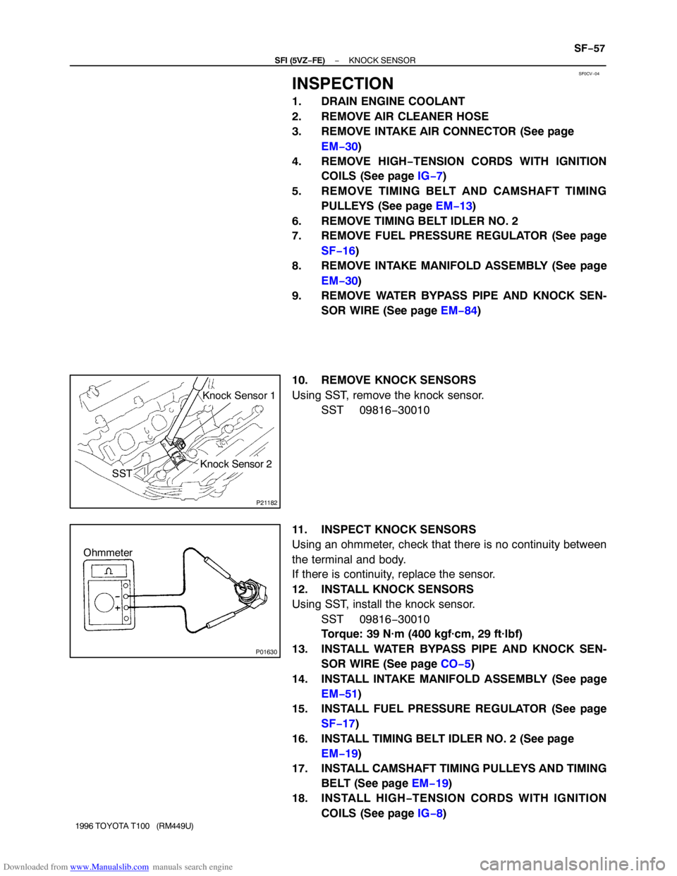
10. REMOVE KNOCK SENSORS
Using SST, remove the knock sensor.
SST 09816−30010
11. INSPECT KNOCK SENSORS
Using an ohmmeter, check that there is no continuity between
the terminal and body.
If there is continuity, replace the sensor.
12. INSTALL KNOCK SENSORS
Using SST, install the knock sensor.
SST 09816−30010
Torque: 39 N·m (400 kgf·cm, 29 ft·lbf)
13. INSTALL WATER BYPASS PIPE AND KNOCK SEN-
SOR WIRE (See page CO−5)
14. INSTALL INTAKE MANIFOLD ASSEMBLY (See page
EM−51)
15. INSTALL FUEL PRESSURE REGULATOR (See page
SF−17)
16. INSTALL TIMING BELT IDLER NO. 2 (See page
EM−19)
17. INSTALL CAMSHAFT TIMING PULLEYS AND TIMING
BELT (See page EM−19)
18. INSTALL HIGH−TENSION CORDS WITH IGNITION
COILS (See page IG−8)
Page 1109 of 2062
Downloaded from www.Manualslib.com manuals search engine CO05R−03
− COOLING (5VZ−FE)WATER PUMP
CO−5
1996 TOYOTA T100 (RM449U)
REMOVAL
1. REMOVE TIMING BELT
(See page EM−13)
2. REMOVE WATER INLET AND THERMOSTAT
3. w/ Oil Cooler:
DISCONNECT NO.2 OIL COOLER HOSE FROM WA-
TER PUMP
4. REMOVE WATER PUMP
Remove the 7 bolts and water pump.
Page 1110 of 2062
Downloaded from www.Manualslib.com manuals search engine CO05S−01
P20920
P21660
P21515
CO−6
− COOLING (5VZ−FE)WATER PUMP
1996 TOYOTA T100 (RM449U)
INSPECTION
1. INSPECT WATER PUMP
(a) Visually check the air hole and water hole for coolant leak-
age.
If leakage is found, replace the water pump.
If engine coolant has leaked onto the timing belt, replace the
timing belt.
(b) Turn the pulley, and check that the water pump bearing
moves smoothly and quietly.
If necessary, replace the water pump.
2. INSPECT FLUID COUPLING
(a) Remove the 4 nuts and fan from the fluid coupling.
(b) Check that the fluid coupling is not damaged and that no
silicon oil leaks.
If necessary, replace the fluid coupling.
3. INSPECT FAN PULLEY BRACKET
(a) Check the turning smoothness of the fan pulley.
If necessary, replace the pulley bracket.
(b) Reinstall the fan to the fluid coupling with the 4 nuts.
Torque:5.4 N·m (75 kgf·cm, 48 in.·lbf)
4. INSPECT TIMING BELT
(See page EM−17)
Page 1111 of 2062
Downloaded from www.Manualslib.com manuals search engine CO05T−02
P20922
Seal Packing
− COOLING (5VZ−FE)WATER PUMP
CO−7
1996 TOYOTA T100 (RM449U)
INSTALLATION
1. INSTALL WATER PUMP
(a) Remove any old packing (FIPG) material and be careful
not to drop any oil on the contact surfaces of the water
pump and cylinder block.
�Using a razor blade and gasket scraper, remove all
the old packing (FIPG) material from the gasket sur-
faces and sealing groove.
�Thoroughly clean all components to remove all the
loose material.
�Using a non−residue solvent, clean both sealing
surfaces.
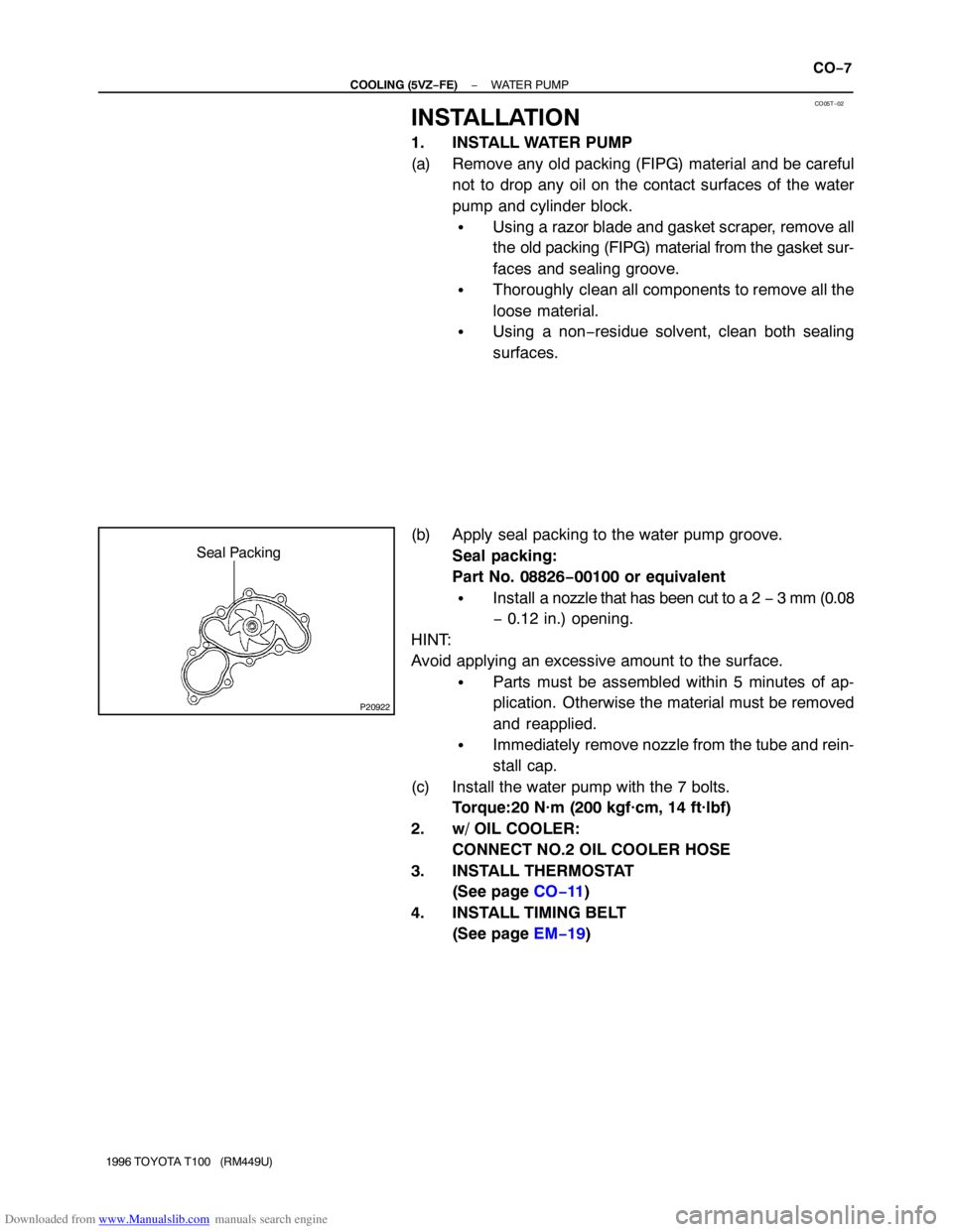
(b) Apply seal packing to the water pump groove.
Seal packing:
Part No. 08826−00100 or equivalent
�Install a nozzle that has been cut to a 2 − 3 mm (0.08
− 0.12 in.) opening.
HINT:
Avoid applying an excessive amount to the surface.
�Parts must be assembled within 5 minutes of ap-
plication. Otherwise the material must be removed
and reapplied.
�Immediately remove nozzle from the tube and rein-
stall cap.
(c) Install the water pump with the 7 bolts.
Torque:20 N·m (200 kgf·cm, 14 ft·lbf)
2. w/ OIL COOLER:
CONNECT NO.2 OIL COOLER HOSE
3. INSTALL THERMOSTAT
(See page CO−11)
4. INSTALL TIMING BELT
(See page EM−19)
Page 1184 of 2062
Downloaded from www.Manualslib.com manuals search engine IG03T−03
P20432
IG−10
− IGNITION (5VZ−FE)CAMSHAFT POSITION SENSOR
1996 TOYOTA T100 (RM449U)
REMOVAL
1. REMOVE UPPER RADIATOR HOSE
2. REMOVE NO. 2 TIMING BELT COVER
(a) Remove the high−tension cord clamps from the No. 2 tim-
ing belt cover.
(b) Remove the PS pump hose from the No. 2 timing belt cov-
er clamp.
(c) Remove the 6 bolts and No. 2 timing belt cover.
3. REMOVE CAMSHAFT POSITION SENSOR
(a) Disconnect the camshaft position sensor connector.
(b) Remove the bolts and camshaft position sensor.
Torque:7.8 N·m (80 kgf·cm, 69 in.·lbf)


