Page 1287 of 2062

Downloaded from www.Manualslib.com manuals search engine MT0501
Down
ClothCounterclockwise
MT04O−02
Q06817
Installation
Front
Select Return Spring
Tip of Shift Lever
− MANUAL TRANSMISSION (R150, R150F)MANUAL TRANSMISSION UNIT (4WD)
MT−7
1996 TOYOTA T100 (RM449U)
REMOVAL
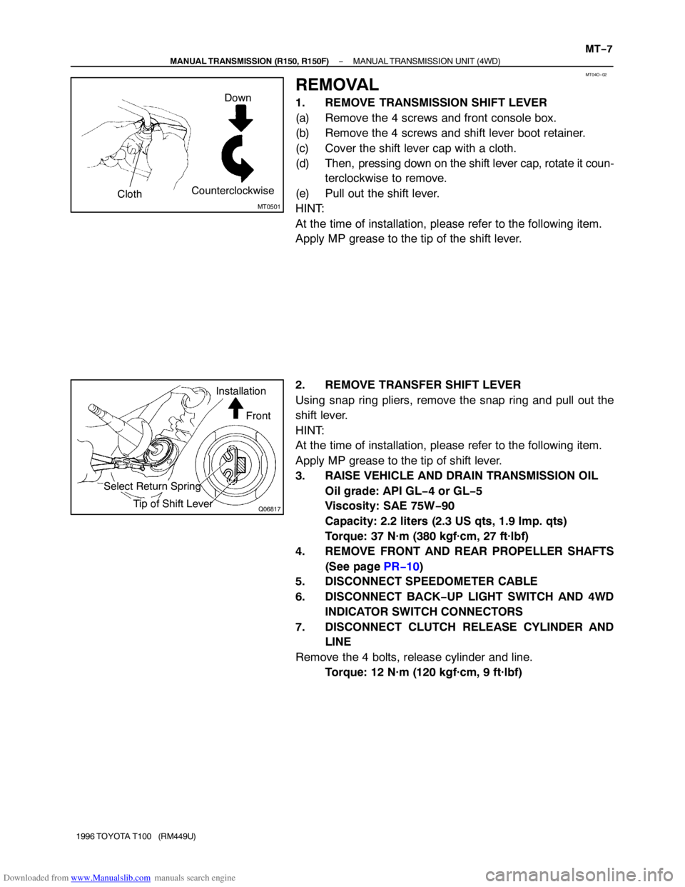
1. REMOVE TRANSMISSION SHIFT LEVER
(a) Remove the 4 screws and front console box.
(b) Remove the 4 screws and shift lever boot retainer.
(c) Cover the shift lever cap with a cloth.
(d) Then, pressing down on the shift lever cap, rotate it coun-
terclockwise to remove.
(e) Pull out the shift lever.
HINT:
At the time of installation, please refer to the following item.
Apply MP grease to the tip of the shift lever.
2. REMOVE TRANSFER SHIFT LEVER
Using snap ring pliers, remove the snap ring and pull out the
shift lever.
HINT:
At the time of installation, please refer to the following item.
Apply MP grease to the tip of shift lever.
3. RAISE VEHICLE AND DRAIN TRANSMISSION OIL
Oil grade: API GL−4 or GL−5
Viscosity: SAE 75W−90
Capacity: 2.2 liters (2.3 US qts, 1.9 Imp. qts)
Torque: 37 N·m (380 kgf·cm, 27 ft·lbf)
4. REMOVE FRONT AND REAR PROPELLER SHAFTS
(See page PR−10)
5. DISCONNECT SPEEDOMETER CABLE
6. DISCONNECT BACK−UP LIGHT SWITCH AND 4WD
INDICATOR SWITCH CONNECTORS
7. DISCONNECT CLUTCH RELEASE CYLINDER AND
LINE
Remove the 4 bolts, release cylinder and line.
Torque: 12 N·m (120 kgf·cm, 9 ft·lbf)
Page 1380 of 2062

Downloaded from www.Manualslib.com manuals search engine AT0ZJ−01
Q07625
AT3168SST
AT0103
AT−12
− AUTOMATIC TRANSMISSIONVALVE BODY ASSEMBLY
1353 Author�: Date�:
1996 TOYOTA T100 (RM449U)
VALVE BODY ASSEMBLY
ON−VEHICLE REPAIR
CAUTION:
When working with FIPG material, you must observe the
followings.
�Using a razor blade and a gasket scraper, remove all
oil FIPG material from the gasket surfaces.
�Remove all loose material to thoroughly clean all
components.
�Clean both sealing surfaces with a non−residue sol-
vent.
�Apply FIPG in an approx. 1 mm (0.04 in.) wide bead
along the sealing surface.
�Parts must be assembled within 10 minutes of ap-
plication. Otherwise, the FIPG material must be re-
moved and reapplied.
1. REMOVE DRAIN PLUG AND DRAIN ATF
Torque: 20 N·m (205 kgf·cm, 15 ft·lbf)
2. REMOVE OIL PAN
NOTICE:
Some fluid will remain in the oil pan.
(a) Remove the 19 bolts.
Torque: 7.4 N·m (75 kgf·cm, 65 in.·lbf)
(b) Install the blade of SST between the transmission case
and oil pan, cut off applied sealer, and remove the oil pan.
SST 09032−00100
NOTICE:
When removing the oil pan, be careful not to damage the oil
pan flange.
3. EXAMINE PARTICLES IN PAN
Remove the magnets and use them to collect steel particles.
Carefully look at the foreign matter and particles in the pan and
on the magnets to anticipate the type of wear you will find in the
transmission.
Steel (magnetic)......bearing, gear and clutch plate wear
Brass (non−magnetic) ...... bushing wear
Page 1384 of 2062
Downloaded from www.Manualslib.com manuals search engine AT1362
Seal Breadth
2 − 3 mm (0.08 − 0.12 in.)
Q07625
AT−16
− AUTOMATIC TRANSMISSIONVALVE BODY ASSEMBLY
1357 Author�: Date�:
1996 TOYOTA T100 (RM449U)
16. INSTALL OIL PAN
(a) A340E:
Install the 4 magnets.
(b) A340F:
Install the 6 magnets.
(c) Remove any packing material and be careful not to drop
oil on the contacting surfaces of the transmission case
and oil pan.
(d) Apply FIPG to the oil pan, as shown in the illustraiton.
FIPG: Part No. 08826−00090, THREE BOND 1281 or
equivalent
(e) Install the oil pan with the 19 bolts.
Torque: 7.4 N·m (75 kgf·cm, 65 in.·lbf)
17. INSTALL DRAIN PLUG
Torque: 20 N·m (205 kgf·cm, 15 ft·lbf)
18. FILL FLUID AND CHECK FLUID
Page 1456 of 2062

Downloaded from www.Manualslib.com manuals search engine PR07Z−01
R15507Matchmarks
R04434
TMC
90Bracket Center
Line
Shaft Axial
Direction
R04435
DANA
90Bracket Center
Line
Shaft Axial
Direction
− PROPELLER SHAFTPROPELLER SHAFT ASSEMBLY (2WD)
PR−9
1996 TOYOTA T100 (RM449U)
INSTALLATION
1. INSTALL PROPELLER SHAFT
(a) Remove SST from the transmission.
SST 09325−40010
(b) Insert the yoke into the transmission.
(c) Temporarily install the center support bearing with 2
mounting bolts.
HINT:
Make sure the bearing is installed with facing the drain hole
downwards.
(d) Align the matchmarks on the flanges and connect the
flanges with the 4 bolts, washers and nuts.
(e) Torque the 4 bolts.
Torque: 74 N·m (750 kgf·cm, 54 ft·lbf)
2. ADJUST CENTER SUPPORT BEARING
HINT:
�With the vehicle unladen, adjust the center support bear-
ing to keep the intervals, as shown.
�At the same condition, check the center line in the axial
direction. Adjust the bearing if necessary.
�Check that the center line of the center bearing is set to
the center line of the bracket when the vehicle is unladen.
Adjust the bracket if necessary.
Torque the 2 bolts.
Torque: 36 N·m (370 kgf·cm, 27 ft·lbf)
Page 1463 of 2062

Downloaded from www.Manualslib.com manuals search engine PR080−01
R04437
Matchmarks
R04440
Matchmarks
Z04758
A
A B
R15508Matchmarks PR−16
− PROPELLER SHAFTPROPELLER SHAFT ASSEMBLY (4WD)
1996 TOYOTA T100 (RM449U)
INSTALLATION
1. INSTALL FRONT PROPELLER SHAFT:
(a) Align the matchmarks on the propeller shaft and differen-
tial flanges, and connect the flanges with the 4 nuts and
washers.
(b) Torque the 4 nuts.
Torque: 74 N·m (750 kgf·cm,54 ft·lbf)
(c) Align the matchmarks on the propeller shaft and transfer
flanges, and connect the flanges with the 4 bolts, washers
and nuts.
(d) Torque the 4 bolts.
Torque: 74 N·m (750 kgf·cm, 54 ft·lbf)
(e) Install the propeller shaft dust cover with the 3 bolts.
Torque:
A bolt: 36 N·m (370 kgf·cm, 27 ft·lbf)
B bolt: 23 N·m (230 kgf·cm, 17 ft·lbf)
(f) M/T:
Install the propeller shaft No.2 dust cover with the 2 bolts
and nuts.
Torque:
Bolt: 17 N·m (175 kgf·cm, 13 ft·lbf)
Nut: 13 N·m (135 kgf·cm, 10 ft·lbf)
2. INSTALL REAR PROPELLER SHAFT
(a) Align the matchmarks on the propeller shaft and transfer
flanges, and connect the flanges with 4 nuts and wash-
ers.
(b) Torque the 4 nuts.
Torque: 76 N·m (780 kgf·cm, 56 ft·lbf)
(c) Temporarily install the center support bearing with 2
mount bolts finger tight.
HINT:
Make sure the bearing is installed with facing the drain hole
downwards.
(d) Align the matchmarks on the flanges, and connect the
flanges with the 4 bolts, washers and nut.
(e) Torque the 4 bolts.
Torque: 76 N·m (780 kgf·cm, 56 ft·lbf)
Page 1517 of 2062

Downloaded from www.Manualslib.com manuals search engine SA0G5−01
R04298
Matchmarks
R04533
FA0858
− SUSPENSION AND AXLEFRONT DIFFERENTIAL CARRIER (4WD)
SA−47
1996 TOYOTA T100 (RM449U)
REMOVAL
1. REMOVE ENGINE UNDER COVER AND DRAIN HYPO-
ID GEAR OIL
2. REMOVE FRONT PROPELLER SHAFT
(See page PR−11)
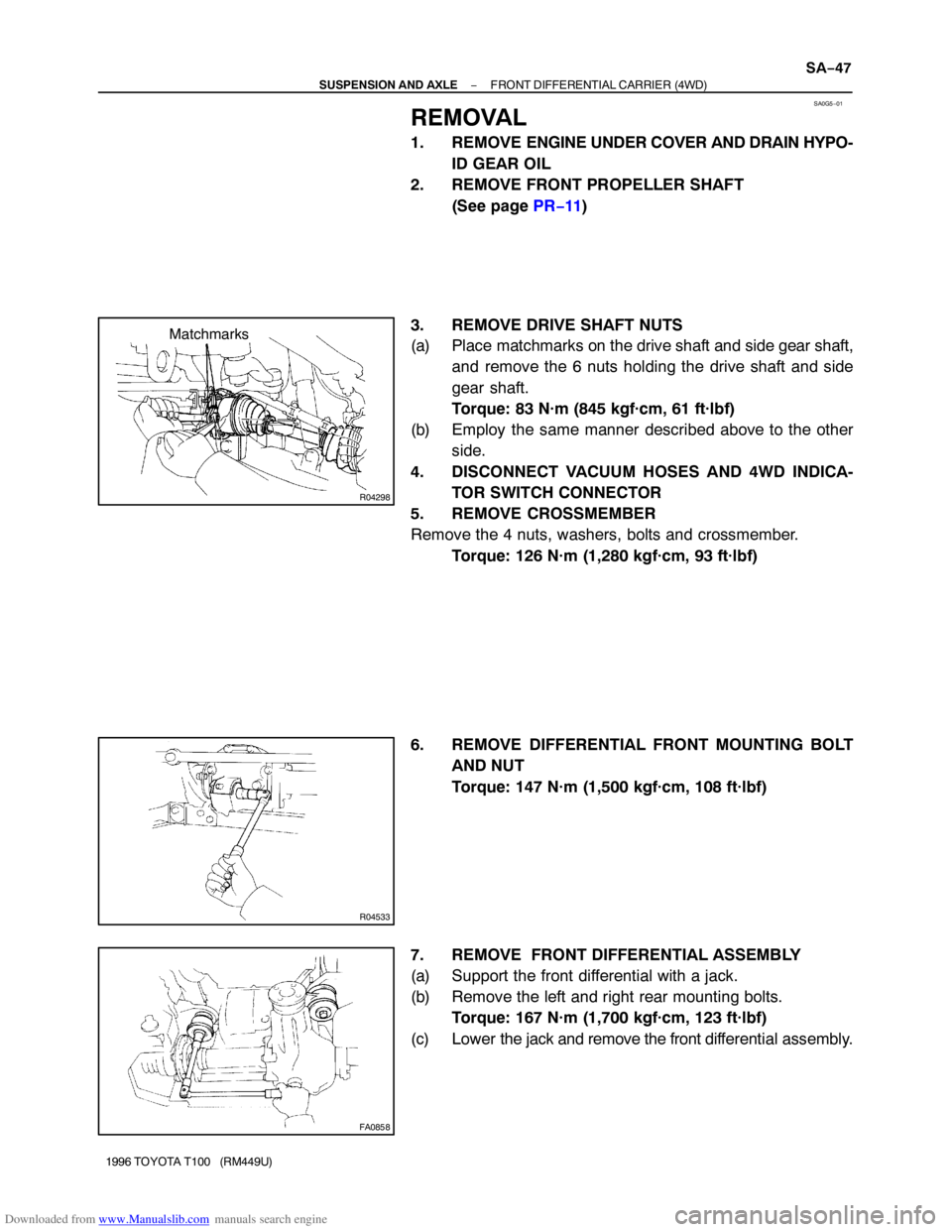
3. REMOVE DRIVE SHAFT NUTS
(a) Place matchmarks on the drive shaft and side gear shaft,
and remove the 6 nuts holding the drive shaft and side
gear shaft.
Torque: 83 N·m (845 kgf·cm, 61 ft·lbf)
(b) Employ the same manner described above to the other
side.
4. DISCONNECT VACUUM HOSES AND 4WD INDICA-
TOR SWITCH CONNECTOR
5. REMOVE CROSSMEMBER
Remove the 4 nuts, washers, bolts and crossmember.
Torque: 126 N·m (1,280 kgf·cm, 93 ft·lbf)
6. REMOVE DIFFERENTIAL FRONT MOUNTING BOLT
AND NUT
Torque: 147 N·m (1,500 kgf·cm, 108 ft·lbf)
7. REMOVE FRONT DIFFERENTIAL ASSEMBLY
(a) Support the front differential with a jack.
(b) Remove the left and right rear mounting bolts.
Torque: 167 N·m (1,700 kgf·cm, 123 ft·lbf)
(c) Lower the jack and remove the front differential assembly.
Page 2033 of 2062
Downloaded from www.Manualslib.com manuals search engine AC0G3−01
I04699
I04700
Heater Radiator Pipe
Water Hose
Hose Clip
Lower
Second RidgeUpper
− AIR CONDITIONINGWATER VALVE
AC−63
1996 TOYOTA T100 (RM449U)
REMOVAL
1. DRAIN ENGINE COOLANT FROM RADIATOR
HINT:
It is not necessary to drain out all coolant.
2. DISCONNECT WATER VALVE CONTROL CABLE
FROM WATER VALVE
HINT:
At the time of installation, please refer to the following item.
After installation, adjust the control cable (See page AC−91).
3. DISCONNECT WATER HOSES
(a) Using pliers grip the claws of hose clip and slide the clip
along the hose.
(b) Disconnect the water hose.
HINT:
At the time of installation, please refer to the following item.
�Push the water hose onto the heater radiator pipe as far
as second ridge on the pipe.
�Push the water hose onto the pipe of water valve pipe as
far as water valve.
4. REMOVE WATER VALVE
Remove the bolt and water valve.