Page 1077 of 2062
Downloaded from www.Manualslib.com manuals search engine SF−58
− SFI (5VZ−FE)KNOCK SENSOR
1996 TOYOTA T100 (RM449U)
19. INSTALL INTAKE AIR CONNECTOR (See page
EM−51)
20. INSTALL AIR CLEANER HOSE
21. FILL WITH ENGINE COOLANT
22. CHECK ENGINE COOLANT LEVEL
Page 1084 of 2062
Downloaded from www.Manualslib.com manuals search engine CO056−02
− COOLING (3RZ−FE)COOLANT
CO−1
1070 Author�: Date�:
1996 TOYOTA T100 (RM449U)
COOLANT
INSPECTION
1. CHECK ENGINE COOLANT LEVEL AT RESERVOIR TANK
The coolant level should be between the ”LOW” and ”FULL” lines.
If low, check for leaks and add coolant up to the ”FULL” line.
2. CHECK ENGINE COOLANT QUALITY
(a) Remove the radiator cap.
CAUTION:
To avoid the danger of being burned, do not remove the radiator cap while the engine and radiator
are still hot, as fluid and steam can be blown out under pressure.
(b) There should not be any excessive deposits of rust or scale around the radiator cap or radiator filler
hole, and the coolant should be free from oil.
If excessively dirty, replace the coolant.
(c) Reinstall the radiator cap.
Page 1085 of 2062
Downloaded from www.Manualslib.com manuals search engine CO057−03
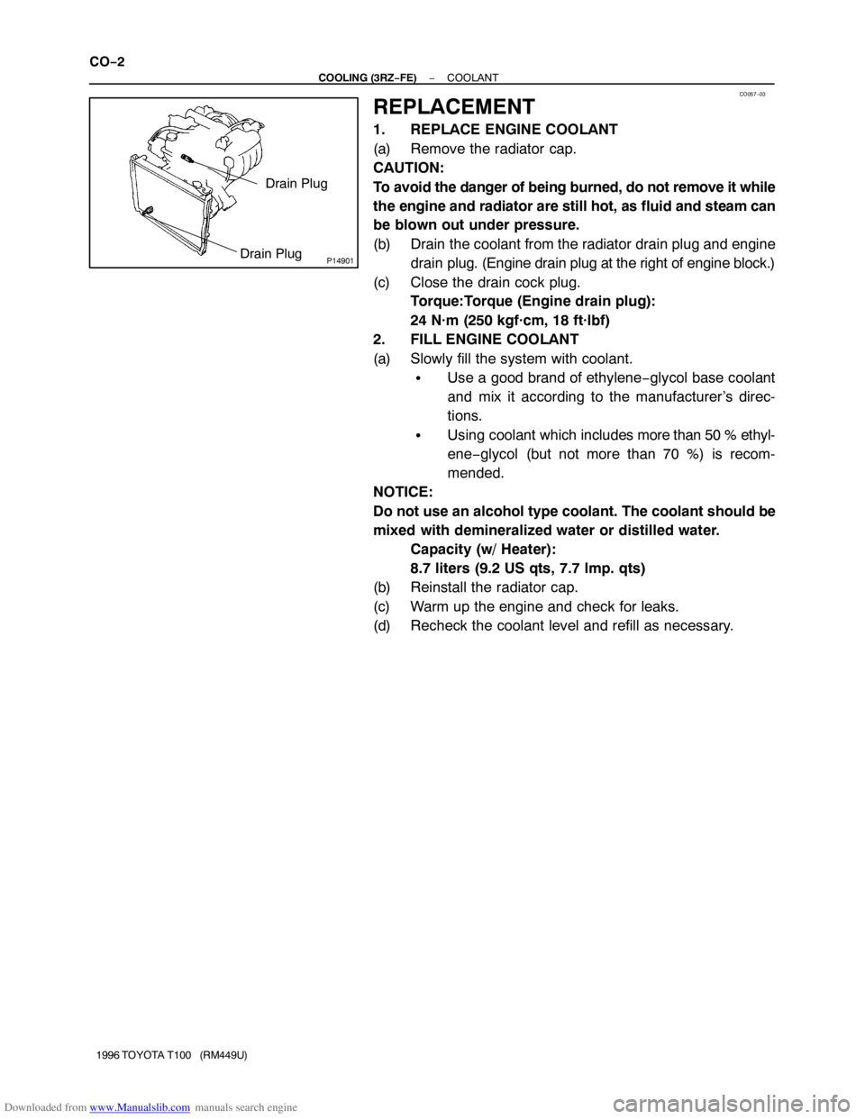
P14901Drain Plug
Drain Plug CO−2
− COOLING (3RZ−FE)COOLANT
1996 TOYOTA T100 (RM449U)
REPLACEMENT
1. REPLACE ENGINE COOLANT
(a) Remove the radiator cap.
CAUTION:
To avoid the danger of being burned, do not remove it while
the engine and radiator are still hot, as fluid and steam can
be blown out under pressure.
(b) Drain the coolant from the radiator drain plug and engine
drain plug. (Engine drain plug at the right of engine block.)
(c) Close the drain cock plug.
Torque:Torque (Engine drain plug):
24 N·m (250 kgf·cm, 18 ft·lbf)
2. FILL ENGINE COOLANT
(a) Slowly fill the system with coolant.
�Use a good brand of ethylene−glycol base coolant
and mix it according to the manufacturer’s direc-
tions.
�Using coolant which includes more than 50 % ethyl-
ene−glycol (but not more than 70 %) is recom-
mended.
NOTICE:
Do not use an alcohol type coolant. The coolant should be
mixed with demineralized water or distilled water.
Capacity (w/ Heater):
8.7 liters (9.2 US qts, 7.7 lmp. qts)
(b) Reinstall the radiator cap.
(c) Warm up the engine and check for leaks.
(d) Recheck the coolant level and refill as necessary.
Page 1105 of 2062
Downloaded from www.Manualslib.com manuals search engine CO05O−01
− COOLING (5VZ−FE)COOLANT
CO−1
1090 Author�: Date�:
1996 TOYOTA T100 (RM449U)
COOLANT
INSPECTION
1. CHECK ENGINE COOLANT LEVEL AT RESERVOIR
TANK
The engine coolant level should be between the
”LOW” and ”FULL” lines, when the engine is cold.
If low, check for leaks and add engine coolant up to the ”FULL”
line.
2. CHECK ENGINE COOLANT QUALITY
(a) Remove the radiator cap from the water outlet.
CAUTION:
To avoid the danger of being burned, do not remove the ra-
diator cap while the engine and radiator are still hot, as fluid
and steam can be blown out under pressure.
(b) There should not be any excessive deposits of rust or
scale around the radiator cap or radiator filler hole, and
the coolant should be free from oil.
If excessively dirty, clean the coolant passages and replace the
coolant.
(c) Reinstall the radiator cap.
Page 1841 of 2062
Downloaded from www.Manualslib.com manuals search engine BE−6
− BODY ELECTRICALBODY ELECTRICAL SYSTEM
1996 TOYOTA T100 (RM449U)
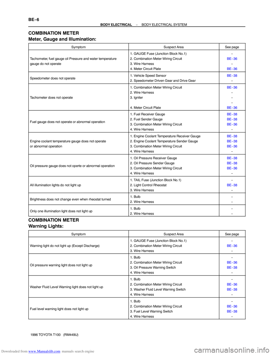
COMBINATION METER
Meter, Gauge and Illumination:
SymptomSuspect AreaSee page
Tachometer, fuel gauge oil Pressure and water temperature
gauge do not operate
1. GAUGE Fuse (Junction Block No.1)
2. Combination Meter Wiring Circuit
3. Wire Harness
4. Meter Circuit Plate−
BE−36
−
BE−36
Speedometer does not operate1. Vehicle Speed Sensor
2. Speedometer Driven Gear and Drive GearBE−38
−
Tachometer does not operate
1. Combination Meter Wiring Circuit
2. Wire Harness
3. Igniter
4. Meter Circuit PlateBE−36
−
−
−
BE−36
Fuel gauge does not operate or abnormal operation
1. Fuel Receiver Gauge
2. Fuel Sender Gauge
3. Combination Meter Wiring Circuit
4. Wire HarnessBE−38
BE−38
BE−36
−
Engine coolant temperature gauge does not operate
or abnormal operation
1. Engine Coolant Temperature Receiver Gauge
2. Engine Coolant Temperature Sender Gauge
3. Combination Meter Wiring Circuit
4. Wire HarnessBE−38
BE−38
BE−36
−
Oil pressure gauge does not operte or abnormal operation
1. Oil Pressure Receiver Gauge
2. Oil Pressure Sender Gauge
3. Combination Meter Wiring Circuit
4. Wire HarnessBE−38
BE−38
BE−36
−
All illumination lights do not light up
1. TAIL Fuse (Junction Block No.1)
2. Light Control Rheostat
3. Wire Harness−
BE−38
−
Brightness does not change even when rheostat turned1. Bulb
2. Wire Harness−
−
Only one illumination light does not light up1. Bulb
2. Wire Harness−
−
COMBINATION METER
Warning Lights:
SymptomSuspect AreaSee page
Warning light do not light up (Except Discharge)
1. GAUGE Fuse (Junction Block No.1)
2. Combination Meter Wiring Circuit
3. Wire Harness−
BE−36
−
Oil pressure warning light does not light up
1. Bulb
2. Combination Meter Wiring Circuit
3. Oil Pressure Warning Switch
4. Wire Harness−
BE−36
BE−38
−
Washer Fluid Level Warning light does not light up
1. Bulb
2. Combination Meter Wiring Circuit
3. Washer Fluid Level Warning Switch
4. Wire Harness−
BE−36
BE−38
−
Fuel level warning light does not light up
1. Bulb
2. Combination Meter Wiring Circuit
3. Fuel Level Warning Switch
4. Wire Harness−
BE−36
BE−38
−
Page 1876 of 2062
Downloaded from www.Manualslib.com manuals search engine N12609
N12610
N06616
Engine Coolant Temperature Gauge
Ignition
Switch
BatterySender
Gauge
N06617
Engine Coolant Temperature Gauge
Test
Bulb
(3.4 W)
− BODY ELECTRICALCOMBINATION METER
BE−41
1996 TOYOTA T100 (RM449U)
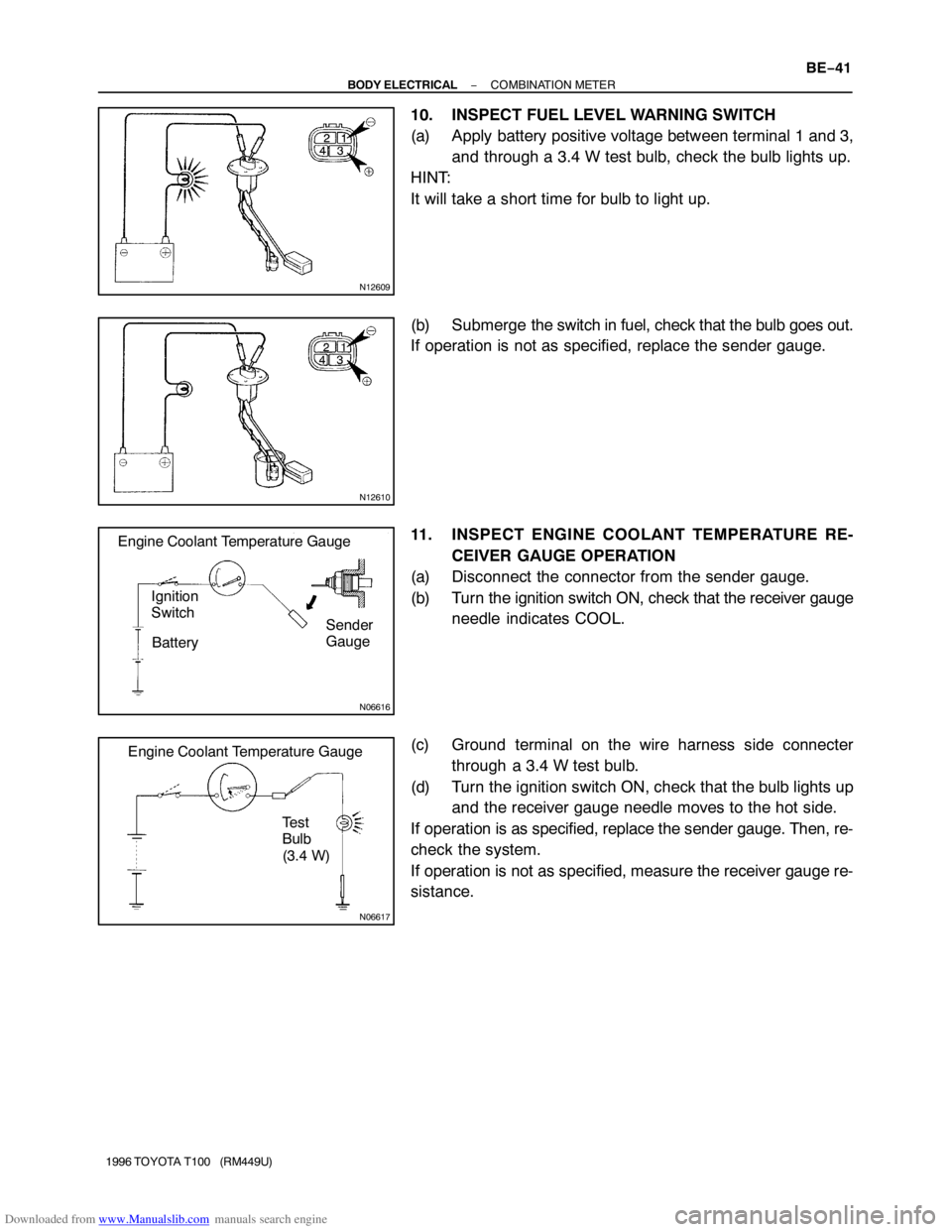
10. INSPECT FUEL LEVEL WARNING SWITCH
(a) Apply battery positive voltage between terminal 1 and 3,
and through a 3.4 W test bulb, check the bulb lights up.
HINT:
It will take a short time for bulb to light up.
(b) Submerge the switch in fuel, check that the bulb goes out.
If operation is not as specified, replace the sender gauge.
11. INSPECT ENGINE COOLANT TEMPERATURE RE-
CEIVER GAUGE OPERATION
(a) Disconnect the connector from the sender gauge.
(b) Turn the ignition switch ON, check that the receiver gauge
needle indicates COOL.
(c) Ground terminal on the wire harness side connecter
through a 3.4 W test bulb.
(d) Turn the ignition switch ON, check that the bulb lights up
and the receiver gauge needle moves to the hot side.
If operation is as specified, replace the sender gauge. Then, re-
check the system.
If operation is not as specified, measure the receiver gauge re-
sistance.