Page 1065 of 1354

Q06273
Q06274
Q06214Matchmarks MX−70
− MANUAL TRANSAXLEDIFFERENTIAL CASE (4WD)
1996 RAV4 (RM447U)
(g) Measure the Plastigage at its widest point.
Standard clearance: 0.16−0.25 mm (0.006−0.010 in.)
(h) Refer to the table below, select the No.2 thrust washer
which will ensure that the backlash is within the specifica-
tion. Try to select a washer of the same size.
MarkThickness mm (in.)MarkThickness mm (in.)
−0.80 (0.0315)−1.15 (0.0453)
−0.85 (0.0335)−1.20 (0.0472)
−0.90 (0.0354)−1.25 (0.0492)
−0.95 (0.0374)−1.30 (0.0512)
−1.00 (0.0394)−1.35 (0.0531)
−1.05 (0.0413)−1.40 (0.0551)
−1.10 (0.0433)−−
(i) Remove the No.2 differential case, No.2 side gear thrust
washer and (temporarily install) a 1.0 mm (0.039 in.) thick
No.2 side gear thrust washer.
11. ASSEMBLE NO.2 DIFFERENTIAL CASE
(a) Install the No.2 side gear thrust washer (previously se-
lected) and conical spring washer to the front differential
case.
HINT:
Be careful not to mistake the direction of the conical spring
washer.
(b) Install the No.2 differential case to the No.1 differential
case.
HINT:
Align the matchmarks on the No.2 differential case and connect
the No.1 differential case.
(c) Install and torque the 16 bolts.
Torque: 124 N·m (1,260 kgf·cm, 91 ft·lbf)
12. ADJUST DIFFERENTIAL CASE SIDE BEARING PRE-
LOAD
(a) Install the differential case assembly to the transaxle
case.
(b) Install the transmission case.
HINT:
If necessary, tap on the transmission case with a plastic ham-
mer.
(c) Install and torque the 17 bolts.
Torque: 29 N·m (300 kgf·cm, 22 ft·lbf)
Page 1066 of 1354

Q06275
− MANUAL TRANSAXLEDIFFERENTIAL CASE (4WD)
MX−71
1996 RAV4 (RM447U)
(d) Turn the differential case assembly right and left 2 or 3
times to allow the bearings to settle.
(e) Using a spring tension gauge, measure the preload.
Preload (at starting):
New bearing (Output shaft preload plus)
31−61 N (3.2−6.3 kgf, 7−14 lbf)
Reused bearing (Output shaft preload plus)
20−39 N (2.0−4.0 kgf, 4−9 lbf)
If the preload is not within the specification, select an appropri-
ate adjusting shim.
HINT:
The total preload will change about 5.1 N (0.5 kgf, 1.1 lbf) for
every 0.05 mm change in adjusting shim thickness.
MarkThickness mm (in.)MarkThickness mm (in.)
02.00 (0.0787)92.45 (0.0965)
12.05 (0.0807)A2.50 (0.0984)
22.10 (0.0827)B2.55 (0.1004)
32.15 (0.0846)C2.60 (0.1024)
42.20 (0.0866)D2.65 (0.1043)
52.25 (0.0886)E2.70 (0.1063)
62.30 (0.0906)F2.75 (0.1083)
72.35 (0.0925)G2.80 (0.1102)
82.40 (0.0945)H2.85 (0.1122)
(f) Remove the 17 bolts, tap the transmission case with a
plastic hammer and remove it.
(g) Remove the differential case assembly.
Page 1135 of 1354

R10840
W01206
2WD M/T RH
W01207
2WD A/T RH
W01208
2WD LH and 4WD RH
W01209
− SUSPENSION AND AXLEFRONT DRIVE SHAFT
SA−21
1996 RAV4 (RM447U)
9. DISCONNECT DRIVE SHAFT FROM AXLE HUB
Using a plastic hammer, disconnect the drive shaft from the axle
hub.
NOTICE:
Be careful not to damage the inner oil seal and ABS speed
sensor rotor.
10. 2WD (M/T) RH:
REMOVE DRIVE SHAFT
NOTICE:
Be careful not to damage the dust cover and oil seal.
(a) Using a screwdriver and hammer, remove the snap ring
from the center bearing bracket.
(b) Remove the bolt from the center bearing bracket.
Torque: 32 N·m (330 kgf·cm, 24 ft·lbf)
(c) Remove the drive shaft with the center drive shaft.
HINT:
If it is hard to remove the bearing, use a brass bar and hammer
and drive flange end of the drive shaft.
(d) Remove the 2 bolts and center bearing bracket.
Torque: 64 N·m (650 kgf·cm, 47 ft·lbf)
11. 2WD (A/T) RH:
REMOVE DRIVE SHAFT
(a) Remove the 2 bolts of the center bearing bracket and pull
out the drive shaft together with the center bearing case
and center drive shaft.
Torque: 64 N·m (650 kgf·cm, 47 ft·lbf)
(b) Remove the center drive shaft with the drive shaft to the
transaxle through the center bearing bracket.
(c) Remove the 3 bolts and center bearing bracket.
Torque: 64 N·m (650 kgf·cm, 47 ft·lbf)
12. 2WD LH:
REMOVE DRIVE SHAFT
(a) Using a brass bar and hammer, remove the drive shaft.
(b) Using a screwdriver, remove the snap ring.
13. 4WD RH:
REMOVE DRIVE SHAFT
(a) Using a brass bar and hammer, remove the drive shaft.
(b) Using a screwdriver, remove the snap ring.
(c) Using a screwdriver, remove the O−ring.
14. 4WD LH:
REMOVE DRIVE SHAFT
(a) Remove the air cleaner.
(b) Remove the transmission case protector.
Torque: 18 N·m (185 kgf·cm, 13 ft·lbf)
(c) Using a hub nut wrench or an equivalent, remove the
drive shaft.
(d) Using a screwdriver, remove the snap ring.
Page 1230 of 1354
S01952
Sound
ScopeSF0QG−02
S01950
Ohmmeter SF−16
− SFIINJECTOR
1996 RAV4 (RM447U)
INJECTOR
ON−VEHICLE INSPECTION
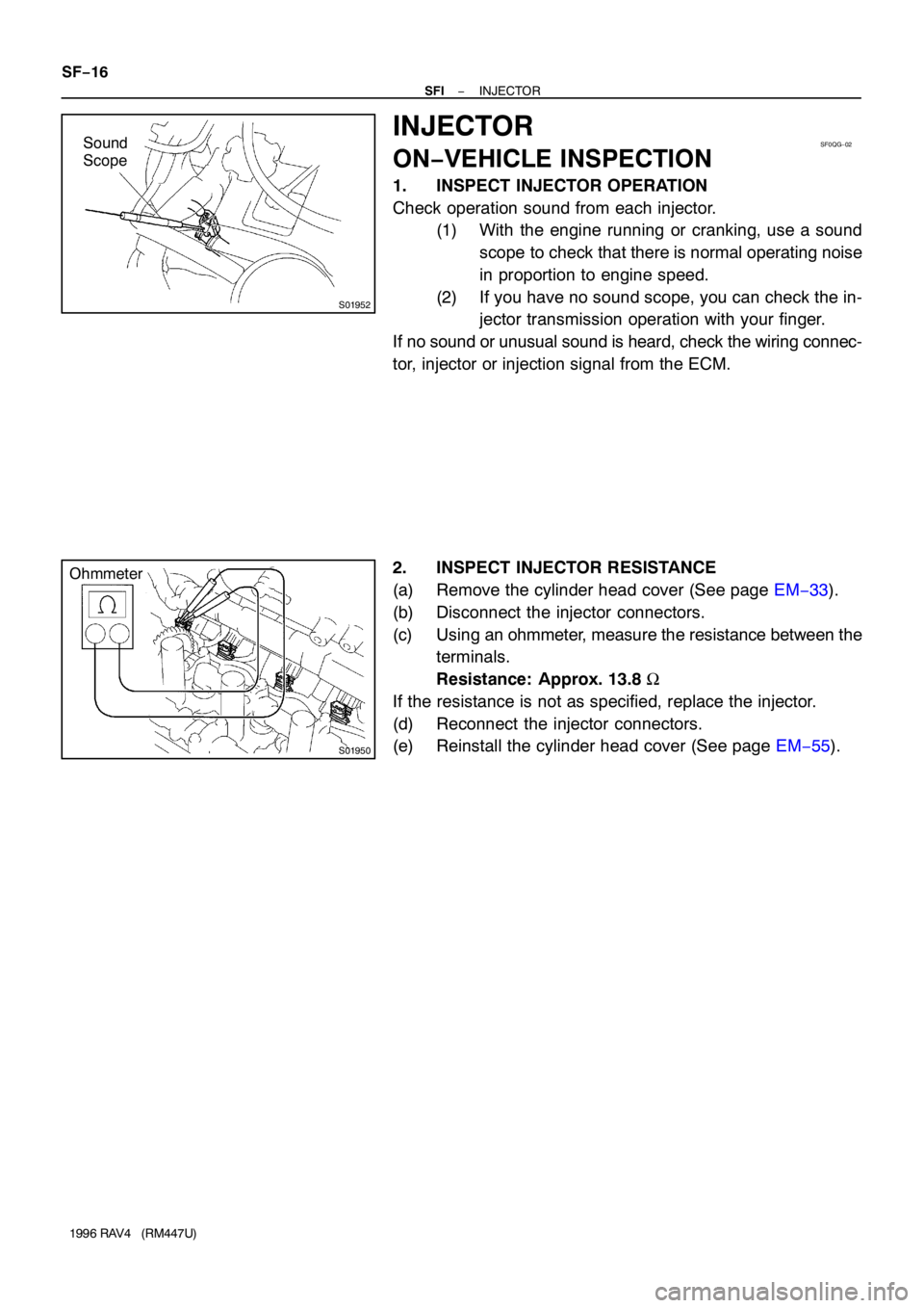
1. INSPECT INJECTOR OPERATION
Check operation sound from each injector.
(1) With the engine running or cranking, use a sound
scope to check that there is normal operating noise
in proportion to engine speed.
(2) If you have no sound scope, you can check the in-
jector transmission operation with your finger.
If no sound or unusual sound is heard, check the wiring connec-
tor, injector or injection signal from the ECM.
2. INSPECT INJECTOR RESISTANCE
(a) Remove the cylinder head cover (See page EM−33).
(b) Disconnect the injector connectors.
(c) Using an ohmmeter, measure the resistance between the
terminals.
Resistance: Approx. 13.8 Ω
If the resistance is not as specified, replace the injector.
(d) Reconnect the injector connectors.
(e) Reinstall the cylinder head cover (See page EM−55).
Page 1248 of 1354
SF0QT−02
S01261
SST DLC1
E1 TE1
S01904
RSC
RSO+B
Ohmmeter
IAC Valve SF−34
− SFIIDLE AIR CONTROL (IAC) VALVE
1996 RAV4 (RM447U)
IDLE AIR CONTROL (IAC) VALVE
ON−VEHICLE INSPECTION
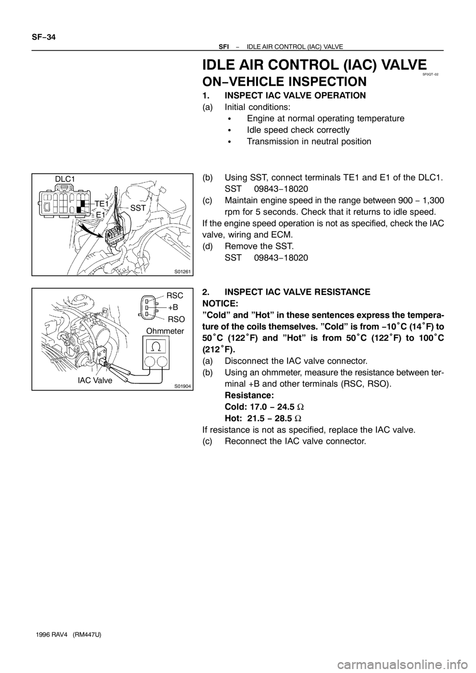
1. INSPECT IAC VALVE OPERATION
(a) Initial conditions:
�Engine at normal operating temperature
�Idle speed check correctly
�Transmission in neutral position
(b) Using SST, connect terminals TE1 and E1 of the DLC1.
SST 09843−18020
(c) Maintain engine speed in the range between 900 − 1,300
rpm for 5 seconds. Check that it returns to idle speed.
If the engine speed operation is not as specified, check the IAC
valve, wiring and ECM.
(d) Remove the SST.
SST 09843−18020
2. INSPECT IAC VALVE RESISTANCE
NOTICE:
”Cold” and ”Hot” in these sentences express the tempera-
ture of the coils themselves. ”Cold” is from −10°C (14°F) to
50°C (122°F) and ”Hot” is from 50°C (122°F) to 100°C
(212°F).
(a) Disconnect the IAC valve connector.
(b) Using an ohmmeter, measure the resistance between ter-
minal +B and other terminals (RSC, RSO).
Resistance:
Cold: 17.0 − 24.5 Ω
Hot: 21.5 − 28.5 Ω
If resistance is not as specified, replace the IAC valve.
(c) Reconnect the IAC valve connector.