Page 529 of 1354
D02268
Rear Speed Sensor
Transfer
Drive
Gear
D02265
Rear Speed Sensor V4 2
1
V4L−Y
R−L
E5E5 14
13
RR
−
RR+
4 − 6 V ECM
− DIAGNOSTICSAUTOMATIC TRANSAXLE (A540H)
DI−209
1996 RAV4 (RM447U)
DTC P1715 Rear Wheel Sensor Circuit Malfunction
(Rear Speed Sensor)
CIRCUIT DESCRIPTION
The rear speed sensor detects the rear wheel speed based on
revolution of the transfer drive gear.
Its construction is the same as that of the front speed sensor
(See page DI−206).
The center differential clutch is controlled by the ECM based on
the signals from the front speed sensor and rear speed sensor
signals.
DTC No.DTC Detecting ConditionTrouble Area
P1715
All conditions below are detected 10 sec. or more
(2 trip detection logic)
(a) No signal rear speed sensor is input to ECM
(b) Vehicle speed: 30 km/h (19 mph) or more
(c) Park / neutral position switch:
OFF (Other than P or N position)
�Open or short in rear speed sensor circuit
�Rear speed sensor
�ECM
WIRING DIAGRAM
DI415−01
Page 535 of 1354

D02275
Current flow to solenoid Center
Differential
Control
Pressure
ON
OFF
1 cycleDuty Ratio =
A + B
A
x 100 (%)
− DIAGNOSTICSAUTOMATIC TRANSAXLE (A540H)
DI−215
1996 RAV4 (RM447U)
DTC P1770 Differential Lock Solenoid No. 1 Circuit
Malfunction (Shift Solenoid Valve SLD)
CIRCUIT DESCRIPTION
Shift solenoid valve SLD controls the oil pressure applied to the
center differential clutch and maintains the limited slip differen-
tial effects at most appropriate level.
The ECM determines optimum control pressure according to
the signals from the throttle position sensor, front and rear
transaxle revolution sensor and control volume of current flow
to the shift solenoid valve.
The amount of current flow to the solenoid valve is controlled
by the duty ratio* of the ECM output signal. The higher the duty
ratio becomes, the higher the center differential control pres-
sure becomes during the center differential control operation.
*: Duty Ratio
The duty ratio is the ratio of the period of continuity in one cycle.
For example, if A is the period of continuity in one cycle, and B
is the period of non−continuity, then
DTC No.DTC Detection ConditionTrouble Area
P1770
All conditions below are detected 1 sec. or more
(2 trip detection logic)
(a) SLD output signal’s duty ON of 3.3 msecs. or more with
duty ratio of at least 5 % lasts
(b) B
+ voltage: 11 V or more
�Open or short in shift solenoid valve SLD circuit
�Shift solenoid valve SLD
�ECM
DI417−01
Page 736 of 1354

S01432
S01285
S01347
EM−70
− ENGINE MECHANICALENGINE UNIT
1996 RAV4 (RM447U)
22. DISCONNECT CONNECTORS, CORD, STRAP AND
HOSES
(a) Disconnect the vapor pressure sensor connector.
(b) Disconnect the igniter connector.
(c) Disconnect the ignition coil connector.
(d) Disconnect the noise filter connector.
(e) Disconnect the high−tension cord from the ignition coil.
(f) Disconnect the MAP sensor connector.
(g) Disconnect the MAP sensor vacuum hose from the gas
filter on the intake manifold.
(h) Disconnect the brake booster hose from the intake man-
ifold.
(i) 4WD M/T:
Disconnect the differential lock control solenoid connec-
tor.
(j) Disconnect the ground strap from the cowl.
23. DISCONNECT ENGINE WIRE FROM CABIN
(a) Remove the RH scuff plate.
(b) Remove the RH cowl side trim.
(c) Remove the RH floor carpet center cover.
(d) Disconnect the 2 ECM connectors.
(e) Disconnect the 2 connectors from the connectors on the
bracket.
(f) Disconnect the connector from the J/B No. 4.
(g) Disconnect the wire clamp from the bracket.
(h) Pull out the engine wire from the cabin.
24. REMOVE FRONT EXHAUST PIPE
(a) Using a 14 mm deep socket wrench, remove the 2 bolts
holding the front exhaust pipe to the front TWC.
(b) Remove the 2 bolts and 2 nuts holding the front exhaust
pipe to the TWC w/ pipe.
(c) Remove the front exhaust pipe and 2 gaskets.
25. DISCONNECT A/C COMPRESSOR FROM ENGINE
(a) Disconnect the A/C compressor connector.
(b) Remove the 2 bolts, nut and stud bolt, and disconnect the
A/C compressor from the engine.
HINT:
Suspend the A/C compressor securely.
26. 4WD only:
REMOVE PROPELLER SHAFT (See page PR−3)
27. REMOVE FRONT DRIVE SHAFT (See page SA−20)
28. REMOVE STABILIZER (See page SA−40)
Page 744 of 1354

S01797
M/T
A/T
S01785
A/T Only
S01351
M/T Only
Back−up Light
Connector EM−78
− ENGINE MECHANICALENGINE UNIT
1996 RAV4 (RM447U)
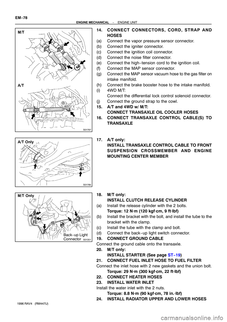
14. CONNECT CONNECTORS, CORD, STRAP AND
HOSES
(a) Connect the vapor pressure sensor connector.
(b) Connect the igniter connector.
(c) Connect the ignition coil connector.
(d) Connect the noise filter connector.
(e) Connect the high−tension cord to the ignition coil.
(f) Connect the MAP sensor connector.
(g) Connect the MAP sensor vacuum hose to the gas filter on
intake manifold.
(h) Connect the brake booster hose to the intake manifold.
(i) 4WD M/T:
Connect the differential lock control solenoid connector.
(j) Connect the ground strap to the cowl.
15. A/T and 4WD w/ M/T:
CONNECT TRANSAXLE OIL COOLER HOSES
16. CONNECT TRANSAXLE CONTROL CABLE(S) TO
TRANSAXLE
17. A/T only:
INSTALL TRANSAXLE CONTROL CABLE TO FRONT
SUSPENSION CROSSMEMBER AND ENGINE
MOUNTING CENTER MEMBER
18. M/T only:
INSTALL CLUTCH RELEASE CYLINDER
(a) Install the release cylinder with the 2 bolts.
Torque: 12 N·m (120 kgf·cm, 9 ft·lbf)
(b) Install the bracket with the bolt, and install the tube to the
bracket with the clamp.
(c) Install the tube with the clamp and bolt.
(d) Connect the back−up light switch connector.
19. CONNECT GROUND CABLE
Connect the ground cable onto the transaxle.
20. M/T only:
INSTALL STARTER (See page ST−19)
21. CONNECT FUEL INLET HOSE TO FUEL FILTER
Connect the inlet hose with 2 new gaskets and the union bolt.
Torque: 29 N·m (300 kgf·cm, 22 ft·lbf)
22. CONNECT HEATER HOSES
23. INSTALL WATER INLET
Install the water inlet with the 2 nuts.
Torque: 8.8 N·m (90 kgf·cm, 78 in.·lbf)
24. INSTALL RADIATOR UPPER AND LOWER HOSES
Page 785 of 1354
15
ABBREVIATIONS D
ABBREVIATIONS
The following abbreviations are used in this manual.
ABS = Anti-Lock Brake System
A/C = Air Conditioning
A/T = Automatic Transaxle
COMB. = Combination
DIFF. = Differential
ECU = Electronic Control Unit
EGR = Exhaust Gas Recirculation
EVAP = Evaporative Emission
J/B = Junction Block
LH = Left-Hand
M/T = Manual Transaxle
O/D = Overdrive
R/B = Relay Block
RH = Right-Hand
SFI = Sequential Multiport Fuel Injection
SRS = Supplemental Restraint System
SW = Switch
TEMP. = Temperature
VSV = Vacuum Switching Valve
w/ = With
w/o = Without
2WD = Two Wheel Drive
4WD = Four Wheel Drive
* The titles given inside the components are the names of the terminals (terminal codes) and are not
treated as being abbreviations.
Page 900 of 1354

131
5. CENTER DIFFERENTIAL CLUTCH CONTROL (4WD)
THE CENTER DIFFERENTIAL CLUTCH CONTROL USES A LINEAR SOLENOID TYPE VALVE (SOLENOID VALVE SLD) TO CONTROL THE
CENTER DIFFERENTIAL CLUTCH. BY CONTROLLING THE FLUID PRESSURE, THE LIMITED SLIP DIFFERENTIAL EFFECT OF THE
CENTER DIFFERENTIAL CAN ALWAYS BE MAINTAINED AT THE OPTIMUM FOR THE CURRENT DRIVING CONDITIONS TO INCREASE
ROAD-HOLDING ABILITY.
SOLENOID VALVE SLD OPENS AND CLOSES IN RESPONSE TO SIGNALS FROM THE ENGINE CONTROL MODULE. THUS THE
SOLENOID MODULATOR VALVE MAINTAINS A CONSTANT FLUID PRESSURE FOR OPERATION OF THE CENTER DIFFERENTIAL
CLUTCH CONTROL VALVE AND CENTER DIFFERENTIAL CLUTCH.
*NORMAL DRIVING
SOLENOID VALVE SLD OPENS AND CLOSES IN RESPONSE TO THE THROTTLE OPENING ANGLE TO CONTROL THE FLUID
PRESSURE OPERATING ON THE CENTER DIFFERENTIAL CLUTCH. WHEN THE VEHICLE TAKES OFF IN FIRST GEAR WITH A
LARGE THROTTLE OPENING ANGLE, THE FLUID PRESSURE IS KEPT HIGH. SO EVEN IF THE VEHICLE TAKES OFF SUDDENLY OR
THE ROAD SURFACE IS SLIPPERY, SMOOTH, RELIABLE ACCELERATION IS POSSIBLE.
*SLIPPING
WHEN A LARGE DIFFERENCE OCCURS BETWEEN THE FRONT WHEEL SPEED AND REAR WHEEL SPEED AT LOW SPEEDS,
SOLENOID VALVE SLD IS FULLY CLOSED TO APPLY HIGH FLUID PRESSURE TO THE CENTER DIFFERENTIAL CLUTCH AND
PROVIDE A LARGE LIMITED SLIP DIFFERENTIAL EFFECT.
*WIDE CORNERING
WHEN DIFFERENCES ARISE BETWEEN THE FRONT WHEEL SPEED AND REAR WHEEL SPEED DUE TO DIFFERENCES IN THE
TURNING RADIUS DURING CORNERING AT LOW SPEEDS, SOLENOID VALVE SLD IS FULLY OPEN TO APPLY A WEAK LIMITED SLIP
DIFFERENTIAL EFFECT AND PERMIT SMOOTH CORNERING.
6. ELECTRONICALLY CONTROLLED TRANSMISSION PATTERN SELECT SW
IF THE ELECTRONICALLY CONTROLLED TRANSMISSION PATTERN SELECT SW IS CHANGED FROM NORMAL TO POWER, THE
CURRENT THROUGH THE POWER INDICATOR FLOWS TO GROUND, CURRENT FLOWS TO TERMINAL P OF THE ENGINE CONTROL
MODULE, THE ENGINE CONTROL MODULE OPERATES, AND SHIFT UP AND SHIFT DOWN OCCURS AT HIGHER VEHICLE SPEEDS
THAN WHEN THE SW IS IN NORMAL POSITION.
Page 996 of 1354

MX01Z−08
− MANUAL TRANSAXLETROUBLESHOOTING
MX−1
1996 RAV4 (RM447U)
TROUBLESHOOTING
PROBLEM SYMPTOMS TABLE
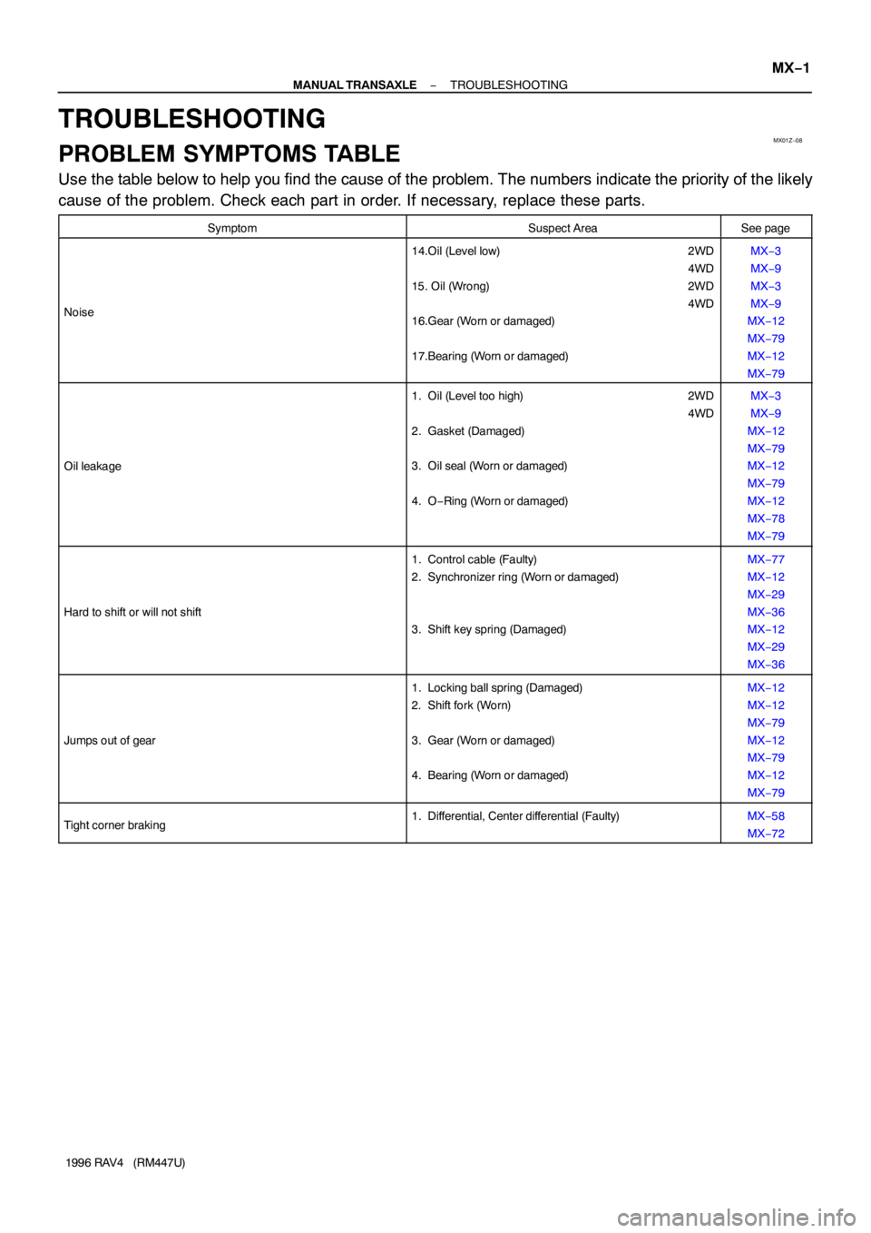
Use the table below to help you find the cause of the problem. The numbers indicate the priority of the likely
cause of the problem. Check each part in order. If necessary, replace these parts.
SymptomSuspect AreaSee page
Noise
14.Oil (Level low) 2WD
4WD
15. Oil (Wrong) 2WD
4WD
16.Gear (Worn or damaged)
17.Bearing (Worn or damaged)MX−3
MX−9
MX−3
MX−9
MX−12
MX−79
MX−12
MX−79
Oil leakage
1. Oil (Level too high) 2WD
4WD
2. Gasket (Damaged)
3. Oil seal (Worn or damaged)
4. O−Ring (Worn or damaged)MX−3
MX−9
MX−12
MX−79
MX−12
MX−79
MX−12
MX−78
MX−79
Hard to shift or will not shift
1. Control cable (Faulty)
2. Synchronizer ring (Worn or damaged)
3. Shift key spring (Damaged)MX−77
MX−12
MX−29
MX−36
MX−12
MX−29
MX−36
Jumps out of gear
1. Locking ball spring (Damaged)
2. Shift fork (Worn)
3. Gear (Worn or damaged)
4. Bearing (Worn or damaged)MX−12
MX−12
MX−79
MX−12
MX−79
MX−12
MX−79
Tight corner braking1. Differential, Center differential (Faulty)MX−58
MX−72
Page 1003 of 1354
MX05R−02
Q09030
Solenoid Hose No.1
Transfer Vacuum Actuator
Bracket
Transfer Vacuum Actuator Assembly
Right Transfer Stiffener Plate
Center Transfer Stiffener Plate
Differential Lock Indicator Switch Connector
Back−Up Light
Switch Connector
Vehicle Speed
Sensor Connector
Transaxle Case Protector
Starter Stiffener Plate
N·m (kgf·cm, ft·lbf): Specified torque
25 (250, 18)
37 (380, 27)
9.0 (95, 78 in.·lbf)
37 (380, 27)
37 (380, 27)
37 (380, 27)
37 (380, 27)
37 (380, 27)
37 (380, 27)
37 (380, 27)
37 (380, 27)
37 (380, 27)
46 (470, 34)
29 (300, 22)
25 (250, 18)
64 (650, 47)
39 (400, 29)
64 (650, 47)
35 (360, 26)
29 (300, 22)
Solenoid Hose No.0
Solenoid Hose No.2
Solenoid Hose No.0 MX−8
− MANUAL TRANSAXLEMANUAL TRANSAXLE UNIT (4WD)
1996 RAV4 (RM447U)
MANUAL TRANSAXLE UNIT (4WD)
COMPONENTS