1996 TOYOTA PASEO ABS
[x] Cancel search: ABSPage 32 of 165

30
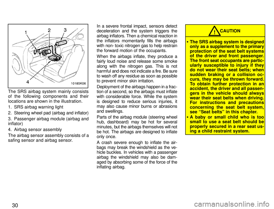
The SRS airbag system mainly consists
of the following components and their
locations are shown in the illustration.
1. SRS airbag warning light
2. Steering wheel pad (airbag and inflator)
3. Passenger airbag module (airbag and inflator)
4. Airbag sensor assembly
The airbag sensor assembly consists of a
safing sensor and airbag sensor.In a severe frontal impact, sensors detect
deceleration and the system triggers the
airbag inflators. Then a chemical reaction in
the inflators momentarily fills the airbags
with non- toxic nitrogen gas to help restrain
the forward motion of the occupants.
When the airbags inflate, they produce a
fairly loud noise and release some smoke
along with the nitrogen gas. This is not
harmful and does not indicate a fire. Be sure
to wash off any residue as soon as possible
to prevent minor skin irritation.
Deployment of the airbags happen in a frac-
tion of a second, so the airbags must inflate
with considerable force. While the system
is designed to reduce serious injuries, it
may also cause minor burns or abrasions
and swellings.
Parts of the airbag module (steering wheel
hub, dashboard) may be hot for several
minutes, but the airbags themselves will not
be hot. The airbags are designed to inflate
only once.
A crash severe enough to inflate the air-
bags may break the windshield as the ve-
hicle buckles. In vehicles with a passenger
airbag the windshield may also be dam-
aged by absorbing some of the force of the
inflating airbag.
CAUTION!
� The SRS airbag system is designed
only as a supplement to the primary
protection of the seat belt systems
of the driver and front passenger.
The front seat occupants are partic-
ularly susceptible to injury if they
do not wear their seat belts; when
sudden braking or a collision oc-
curs, they may be thrown forward.
To obtain further protection in an
accident, the driver and all passen-
gers in the vehicle should alwayswear their seat belts when driving.
For instructions and precautions
concerning the seat belt system,
see Seat beltsº in this chapter.
� A baby or small child who is too
small to use a seat belt should be
properly secured in a rear seat us- ing a child restraint system.
Page 60 of 165

57
(a) Malfunction Indicator Lamp
This lamp comes on in the following cases.
a. The fuel tank is completely empty.
(See Fuel gaugeº in Chapter 1-5 for in- structions.)
b. There is a
problem somewhere in your
engine or automatic transmission electri- cal system.
If it comes on while you are driving in case
b, have your vehicle checked/repaired by
your Toyota dealer as soon as possible.
(b) Low Fuel Level Warning Light
This light comes on when the fuel level in
the tank becomes nearly empty. Fill up the
tank as soon as possible.
(c) ABSº Warning Light
This light warns that there is a problem
somewhere in your anti-lock brake sys- tem.
If the light comes on while you are driving,
have your vehicle checked by your T oyota
dealer as soon as possible.
The light comes on when the ignition key
is turned to the ONº position. After about
3 seconds, the light will go off. When the ABSº warning light is on (and
the brake system warning light is off), the brake system
operates conventionally but
without anti-lock function.
(d) Open Door Warning Light
This light remains on until both side doors
are completely closed.
(e) SRS Airbag Warning Light
This light will come on when the igni-
tion key is turned to the ACCº or ONº
position. After about 6 seconds, the
light will go off. This means the airbag
system is operating properly.
The warning light system monitors the air
bag sensor assembly, inflators, warning
light, interconnecting wiring and power sources.
If either of the following conditions occurs, this indicates a malfunction somewhere in the parts monitored by the warning light
system. Contact your Toyota dealer as
soon as possible to service the vehicle. � The light does not come on when the
ignition key is turned to the ACCº or
ONº position or remains on.
� The light comes on while driving. (f) Light Reminder Buzzer
The buzzer will sound if the driver's door is opened with the key removed from the
ignition switch and the headlight switch
left on.
(g) Key Reminder Buzzer
This buzzer reminds you to remove the
key when you open the driver's door with the ignition key in the ACCº or LOCKºposition.
CHECKING SERVICE REMINDER
INDICATORS
1. Apply the parking brake.
2. Open either side door.
The open door warning light should come on.
3. Close the door.
The open door warning light should go off.
4. Turn the ignition key to ACCº.
The SRS airbag warning light should
come on. It goes off after about 6 sec- onds.
Page 61 of 165

585. Turn the ignition key to ONº, but do not
start the engine.
All the service reminder indicators except the open door warning light and SRS air-
bag warning light should come on. The
ABSº warning light goes off after about 3seconds.
If any service reminder indicator or warning
buzzer does not function as described
above, either the bulb is burned out or the
circuit is in need of repair. Have it checked
by your Toyota dealer as soon as possible.
Page 95 of 165

92
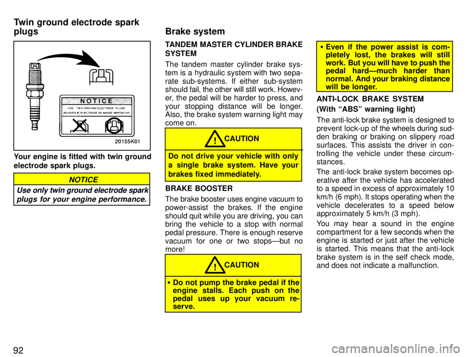
Your engine is fitted with twin ground electrode spark plugs.
Use only twin ground electrode sparkplugs for your engine performance.
NOTICE
TANDEM MASTER CYLINDER BRAKE SYSTEM
The tandem master cylinder brake sys-
tem is a hydraulic system with two sepa-
rate sub-systems. If either sub-system
should fa il, the other will still work. Howev-
er, the pedal will be harder to press, and
your stopping distance will be longer.
Also, the brake system warning light may come on.
CAUTION!
Do not drive your vehicle with only
a single brake system. Have your
brakes fixed immediately.
BRAKE BOOSTER
The brake booster uses engine vacuum to
power-assist the brakes. If the engine
should quit while you are driving, you can
bring the vehicle to a stop with normal
pedal pressure. There is enough reservevacuum for one or two stopsÐbut no more!
CAUTION!
� Do not pump the brake pedal if the
engine stalls. Each push on the
pedal uses up your vacuum re- serve.
�Even if the power assist is com-
pletely lost, the brakes will still
work. But you will have to push the
pedal hardÐmuch harder than
normal. And your braking distance
will be longer.
ANTI-LOCK BRAKE SYSTEM (With ABSº warning light)
The anti-lock brake system is designed to prevent lock-up of the wheels during sud-
den braking or braking on slippery roadsurfaces. This assists the driver in con-
trolling the vehicle under these circum- stances.
The anti-lock brake system becomes op- erative after the vehicle has accelerated
to a speed in excess of approximately 10
km/h (6 mph). It stops operating when the
vehicle decelerates to a speed below
approximately 5 km/h (3 mph).
You may hear a sound in the engine
compartment for a few seconds when the
engine is started or just after the vehicleis started. This means that the anti-lock
brake system is in the self check mode,
and does not indicate a malfunction.
Brake system
Twin ground electrode spark plugs
Page 97 of 165

94ABSº warning light
This light comes on when the ignition key is turned to the ONº position. After about
3 seconds, the light will go off.
If either of the following conditions occurs, this indicates a malfunction somewhere inthe parts monitored by the warning light
system. Contact your Toyota dealer as
soon as possible to service the vehicle. �
The light does not come on as de-
scribed above, or remains on.
� The light comes on while driving.
Even if the anti-lock brake system should
fail, the brake system will still operate con-
ventionally. Have your vehicle checked
by your Toyota dealer as soon as pos- sible.
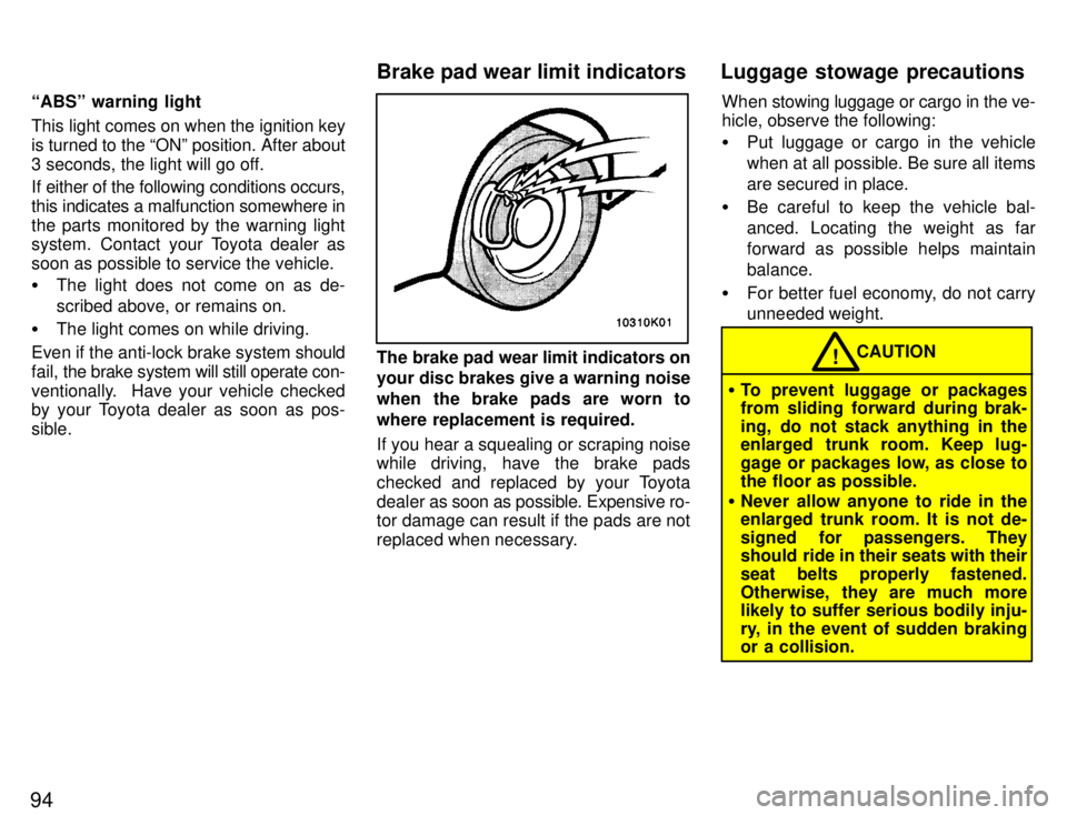
The brake pad wear limit indicators on your disc brakes give a warning noise
when the brake pads are worn to
where replacement is required.
If you hear a squealing or scraping noise
while driving, have the brake pads
checked and replaced by your Toyota
dealer as soon as possible. Expensive ro-
tor damage can result if the pads are not
replaced when necessary. When stowing luggage or cargo in the ve-
hicle, observe the following: �
Put luggage or cargo in the vehicle
when at all possible. Be sure all itemsare secured in place.
� Be careful to keep the vehicle bal-anced. Locating the weight as far
forward as possible helps maintainbalance.
� For better fuel economy, do not carry
unneeded weight.
�To prevent luggage or packages
from sliding forward during brak-
ing, do not stack anything in the
enlarged trunk room. Keep lug-
gage or packages low, as close to
the floor as possible.
� Never allow anyone to ride in the enlarged trunk room. It is not de-
signed for passengers. They
should ride in their seats with their
seat belts properly fastened.
Otherwise, they are much more
likely to suffer serious bodily inju-
ry, in the event of sudden braking
or a collision.
CAUTION!
Brake pad wear limit indicators Luggage stowage precautions
Page 141 of 165

138To check the fluid level, simply look at
the see-through reservoir. The level
should be between the MAXº and
MINº lines on the reservoir. It is normal for the brake fluid level to go
down slightly as the brake pads wear. So be sure to keep the reservoir filled.
If the reservoir needs frequent refilling, it may indicate a serious mechanical prob- lem.
If the level is low, add SAE J1703 or
FMVSS No. 116 DOT 3 brake fluid to the
brake reservoir. Remove and replace the reservoir cover
by hand. Fill the brake fluid to the dotted
line.
This brings the fluid to the correct lev-
el when you put the cover back on. Use only newly opened brake fluid. Once
opened, brake fluid absorbs moisture
from the air, and excess moisture can cause a dangerous loss of braking.
CAUTION
Take care when filling the reservoir
because brake fluid can harm your
eyes and damage painted surfaces. If
fluid gets in your eyes, flush your
eyes with clean water.!
If you spill the fluid, be sure to wash
it off with water to prevent it from
damaging the parts or paint.
NOTICE
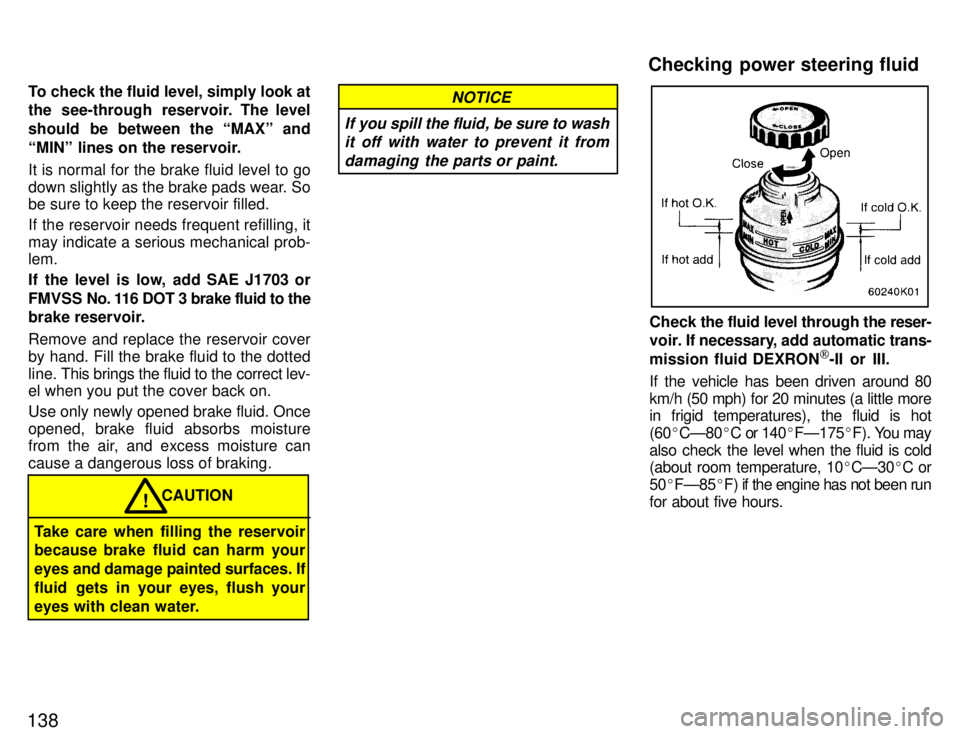
Check the fluid level through the reser-
voir. If necessary, add automatic trans-
mission fluid DEXRON [
-II or III.
If the vehicle has been driven around 80
km/h (50 mph) for 20 minutes (a little more
in frigid temperatures), the fluid is hot
(60 �CÐ80 �C or 140 �FÐ175 �F). You may
also check the level when the fluid is cold
(about room temperature, 10 �CÐ30 �C or
50 �FÐ85 �F) if the engine has not been run
for about five hours.
Checking power steering fluid
Page 155 of 165

152
3. Release the bulb retaining spring
and remove the bulb. Install a new
bulb and the bulb retaining spring.
To install a bulb, align the tabs of the bulb with the cutouts of the mounting hole.4. Install the rubber cover with the
TOPº mark upward, and snuggle on
the boss. Insert the connector. Then
install the plastic cover.
Make sure the rubber cover fits snugly on
the connector and the headlight body.
Aiming is not necessary after replacing
the bulb. When aiming adjustment is nec-
essary, contact your Toyota dealer.Use a Phillips-head screwdriver.
ÐParking, front side marker and front turn signal lights
Page 162 of 165

159
Instrument panel 17. GAUGE 10 A: Gauge and meters,
service reminder indicators and warning
buzzers (except discharge and open door
warning lights), back-up lights, rear win-
dow defogger
18. TURN 7.5 A: Turn signal lights, emer-
gency flashers19. WIPER 20 A: Windshield wipers and
washer
20. ECU-IG 5 A: Anti-lock brake system,
air conditioning system 21. CIG&RADIO 15 A: Cigarette lighter,
car audio system, clock, anti-lock brake
system, theft deterrent system, shift lockcontrol systemInstrument panel
22. IGN 5 A: Charging system, discharge
warning light, multiport fuel injection sys- tem/sequential multiport fuel injection
system, SRS airbag system 23. SRS 5 A: SRS airbag warning light
Fuses (type B)
24. CDS FAN 30 A: Electric cooling fan
25. RAD FAN 30 A: Electric cooling fan
26. HEATER 40 A: Air conditioning sys-
tem, A/Cº fuse 27. DIMMER 30 A: HEAD RH (Lo)º,
HEAD LH (Lo)º, HEAD RH (Hi)º and
HEAD LH (Hi)º fuses 28. MAIN 30 A: Starter system 29. DEF 40 A:
Rear window defogger
30. PWR 30 A: Power windows, power
door lock systemFuses (type C) 31. ABS 60 A: Anti-lock brake system
32. AM1 40 A: DEFº, WIPERº,
GAUGEº, ECU-IGº, TURNº, IGNº and
PWRº fuses
33. ALT 100 A: ABSº, STOPº, TAILº,
SRSº, DEFº, AM1º, WIPERº,
GAUGEº, ECU-IGº, TURNº, IGNº and
PWRº fuses