Page 1324 of 1399

AUTOMATIC TRANSMISSION
SERVICE DATA
Line pressure (Wheel locked)
Engine idling")
SS1E6−02
−
SERVICE SPECIFICATIONS AUTOMATIC TRANSMISSION
SS−23
146
Author�: Date�:
1996 LAND CRUISER (RM451U)
AUTOMATIC TRANSMISSION
SERVICE DATA
Line pressure (Wheel locked)
Engine idling D position R position
AT stall (Throttle valve fully opened) D position R position
422 − 481 kPa (4.3 − 4.9 kgf/cm2, 61 − 70 psi)
510 − 608 kPa (5.2 − 6.2 kgf/cm2, 74 − 88 psi)
1,285 − 1,530 kPa (13.1 − 15.6 kgf/cm2, 128 − 153 psi)
1,579 − 1,932 kPa (16.1 − 19.7 kgf/cm2, 158 − 193 psi)
Engine stall revolution D and R position1,950 ± 150 rpm
Time lag N → D position
N → R positionLess than 1.2 seconds
Less than 1.5 seconds
Engine idle speed (A/C OFF) N position650 ± 50 rpm
Throttle cable adjustment (throttle valve fully closed)
Between boot and face and inner cable stopper
0 −1 mm (0 − 0.04 in.)
Torque converter clutch installation distance
Drive plate runout Max.
Torque converter clutch runout Max.More than 15.7 mm (0.618 in.)
0.20 mm (0.0079 in.)
0.30 mm (0.0118 in.)
Shift point
D position
Throttle valve fully opened 1 → 2
2 → 3
3 → O/D
O/D → 3
3 → 2
2 → 1
2 position
Throttle valve fully opened 3 → 2
L position
Throttle valve fully opened 2 → 1
56 − 62 km/h (35 − 39 mph)
103 − 114 km/h (64 − 71 mph)
152 − 163 km/h (94 − 101 mph)
145 − 156 km/h (90 − 97 mph)
95 − 101 km/h (59 − 63 mph)
42 − 47 km/h (26 − 29 mph)
116 − 127 km/h (72 − 79 mph)
56 − 62 km/h (38 − 39 mph)
Lock−up point Throttle valve opening 5 %
D position Lock −up ON
Lock− up OFF
77 − 83 km/h (48 − 52 mph)
68 − 74 km/h (42 − 46 mph)
Brought to you by BirfMark
Brought to you by BirfMark
Version 1.11 - 03/16/2010
Page 1325 of 1399

TORQUE SPECIFICATION
Part tightenedN·mkgf·cmft·lbf
Valve body x Transmission case101007
Oil staine")
SS1E7−01
SS−24
−
SERVICE SPECIFICATIONS AUTOMATIC TRANSMISSION
1996 LAND CRUISER (RM451U)
TORQUE SPECIFICATION
Part tightenedN·mkgf·cmft·lbf
Valve body x Transmission case101007
Oil stainer x Valve body101007
Oil pan7.47565 in.·lbf
Drain plug x Oil pan2020515
Parking lock pawl bracket x Transmission case7.47565 in.·lbf
Front propeller shaft x Front dif ferential7475054
Front propeller shaft x Transfer7475054
Rear propeller shaft x Transfer8890065
Rear propeller shaft x Rear dif ferential8890065
Drive plate x Crankshaft981,00072
Torque converter clutch x Drive plate5555040
Front exhaust pipe x Exhaust manifold6263046
Front exhaust pipe x TWC3940029
Oil cooler pipe3435025
Transmission x Engine7173053
Exhaust pipe clamp1919514
Park/neutral position switch Nut
Bolt6.9 1370
13061 in.·lbf 9
No. 2 vehicle speed sensor5.45548 in.·lbf
Speedometer driven gear sleeve x Locking plate1616012
Starter mounting bolt3940029
Transfer shift lever1818513
Stabilizer bar bracket mounting bolt1818513
Engine under cover mounting bolt2829021
Exhaust pipe No. 1 support bracket x Torque converter clutch housing2424017
Crossmember x Frame6162045
Engine rear mounting x Crossmember7475054
Transmission shift lever assembly x Body5.45548 in.·lbf
Oil cooler mounting bolt1111 58
Brought to you by BirfMark
Brought to you by BirfMark
Version 1.11 - 03/16/2010
Page 1344 of 1399
SS1EL−01
−
SERVICE SPECIFICATIONS AIR CONDITIONING
SS−43
166
Author�: Date�:
1996 LAND CRUISER (RM451U)
AIR CONDITIONING
SERVICE DATA
Refrigerant charge volume850 ± 50 g (59.98 ± 1.76 oz.)
Drive belt tension New belt
Used belt100 � 150 lbf
60 � 100 lbf
Idle− up speed800 rpm
Magnetic clutch clearance0.5 ± 0.15 mm (0.020 ± 0.0059 in.)
Brought to you by BirfMark
Brought to you by BirfMark
Version 1.11 - 03/16/2010
Page 1350 of 1399

DISASSEMBLY
HINT:
At the time of reassembly, use high−temperature grease to lu-
bricate the bearings,")
ST0KQ−01
P23005
P23006
P08385
P23007
−
STARTING STARTER
ST−5
1996 LAND CRUISER (RM451U)
DISASSEMBLY
HINT:
At the time of reassembly, use high−temperature grease to lu-
bricate the bearings, gears, return spring and steel ball when
assembling the starter.
1. REMOVE FIELD FRAME AND ARMATURE
(a) Remove the nut, and disconnect the lead wire from the
magnetic switch terminal.
Torque: 5.9 N·m (60 kgf·cm, 52 in.·lbf)
(b) Remove the 2 through bolts. Torque:
1.4 kW type: 5.9 N·m (60 kgf·cm, 52 in.·lbf)
2.0 kW type: 9.3 N·m (95 kgf·cm, 82 in.·lbf)
(c) Pull out the field frame with the armature from the magnet-
ic switch assembly.
(d) Remove the O−ring.
HINT:
At the time of reassembly, use a new O−ring.
HINT:
At the time of reassembly, align the protrusion of the field frame
with cutout of the magnetic switch.
2. REMOVE STARTER HOUSING, CLUTCH ASSEMBLY AND GEAR
(a) Remove the 2 screws.
Torque:
1.4 kW type: 5.9 N·m (60 kgf·cm, 52 in.·lbf)
2.0 kW type: 9.3 N·m (95 kgf·cm, 82 in.·lbf)
Brought to you by BirfMark
Brought to you by BirfMark
Version 1.11 - 03/16/2010
Page 1351 of 1399
P04683(1) (5)(4)
(2)
(3)
P04515
Magnetic Finger
P23004
P04525
ST−6
−
STARTING STARTER
1996 LAND CRUISER (RM451U)
(b) Remove these parts from the magnetic switch assembly:
(1) Starter housing
(2) Return spring
(3) Bearing
(4) Idler gear
(5) Starter clutch assembly
3. REMOVE STEEL BALL
Using a magnetic finger, remove the steel ball from the clutch
shaft hole.
4. REMOVE BRUSH HOLDER
(a) Remove the 2 screws, 2 O −rings and end cover from the
field frame.
Torque:
1.4 kW type: 1.5 N·m (15 kgf·cm, 13 in.·lbf)
2.0 kW type: 3.8 N·m (40 kgf·cm, 35 in.·lbf)
HINT:
At the time of reassembly, use new O−rings.
(b) Remove the O−ring from the field frame.
HINT:
At the time of reassembly, use a new O−ring.
(c) Using a screwdriver, hold the spring back and disconnect
the brush from the brush holder. Disconnect the four
brushes and remove the brush holder.
5. REMOVE ARMATURE FROM FIELD FRAME
Brought to you by BirfMark
Brought to you by BirfMark
Version 1.11 - 03/16/2010
Page 1354 of 1399

Minimum spring installed load:
1.4 kW type: 11.8 N (1.20 kgf, 2.7 lbf)
2.0 kW type: 12.7 N (1.29")
P21088
OhmmeterNo Continuity
P10821
Lock
Free
−
STARTING STARTER
ST−9
1996 LAND CRUISER (RM451U)
Minimum spring installed load:
1.4 kW type: 11.8 N (1.20 kgf, 2.7 lbf)
2.0 kW type: 12.7 N (1.29 kgf, 2.9 lbf)
If the installed load is less than minimum replace the brush
springs.
11. INSPECT BRUSH HOLDER INSULATION
Using an ohmmeter, check that there is no continuity between
the positive (+) and negative ( −) brush holders.
If there is continuity, repair or replace the brush holder.
12. INSPECT GEAR TEETH
Check the gear teeth on the pinion gear, idler gear and clutch
assembly for wear or damage.
If damaged, replace the gear or clutch assembly.
If damaged, also check the drive plate ring gear for wear or
damage.
13. INSPECT CLUTCH PINION GEAR
Hold the starter clutch and rotate the pinion gear clockwise, and
check that it turns freely. Try to rotate the pinion gear counter-
clockwise and check that it locks.
If necessary, replace the clutch assembly.
14. INSPECT REAR BEARING
Turn each bearing by hand while applying inward force.
If resistance is felt or the bearing sticks, replace the bearing.
15. INSPECT FRONT BEARING
Turn each bearing by hand while applying inward force.
If resistance is felt or the bearing sticks, replace the bearing.
Brought to you by BirfMark
Brought to you by BirfMark
Version 1.11 - 03/16/2010
Page 1361 of 1399

ST08H−03
P23047
Terminal CBattery
Terminal 50
P23049
Disconnect
Battery
P23048
DIsconnect
Battery
P23050
Terminal 30 AmmeterBattery
Terminal 50
ST−16
−
STARTING STARTER
1996 LAND CRUISER (RM451U)
TEST
NOTICE:
These tests must be performed within 3 to 5 seconds to
avoid burning out the coil.
1. DO PULL−IN TEST
(a) Disconnect the field coil lead wire from terminal C.
(b) Connect the battery to the magnetic switch as shown.
Check that the clutch pinion gear moves outward.
2. DO HOLD−IN TEST
With battery connected as above with the clutch pinion gear
out, disconnect the negative ( −) lead from terminal C. Check
that the pinion gear remains out.
3. INSPECT CLUTCH PINION GEAR RETURN
(a) Disconnect the negative ( −) lead from the switch body.
(b) Check that the clutch pinion gear returns inward.
4. DO NO−LOAD PERFORMANCE TEST
(a) Connect the battery and ammeter to the starter as shown.
(b) Check that the starter rotates smoothly and steadily with
the pinion gear moving out. Check that the ammeter
shows the specified current.
Specified current:
1.4 kW type
At 11.5V: 90 A or less
2.0 kW type
At 11.5V: 100 A or less
Brought to you by BirfMark
Brought to you by BirfMark
Version 1.11 - 03/16/2010
Page 1364 of 1399
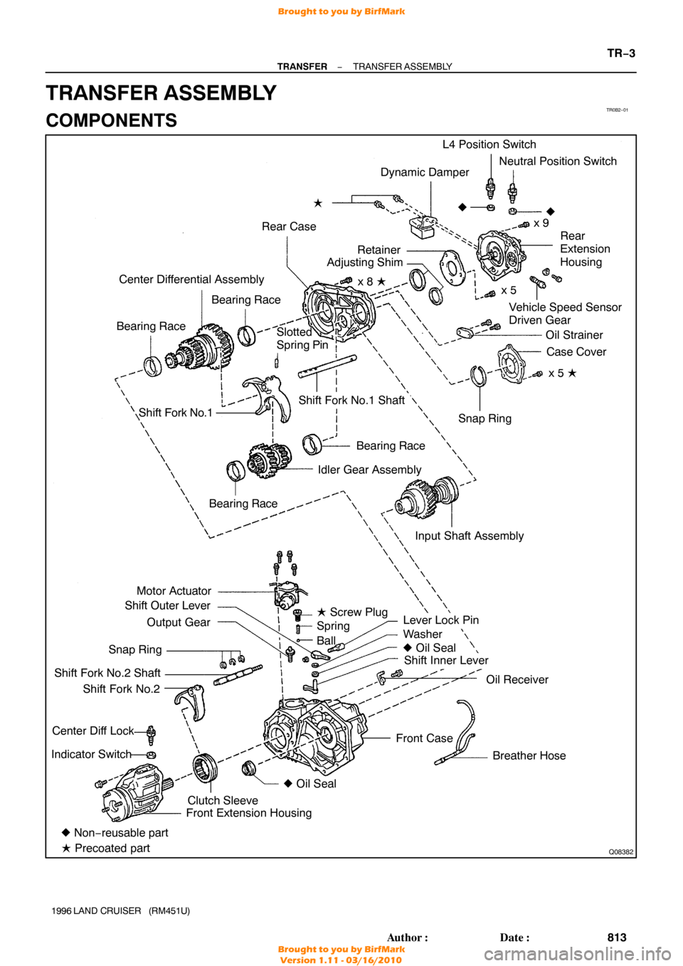
TR0B2−01
Q08382
Dynamic Damper
Rear Case �
Vehicle Speed Sensor
Driven Gear
Center Differential Assembly
Bearing Race
Bearing Race L4 Position Switch
Neutral Position Switch
x 9
�
Rear
Extension
Housing
Oil Strainer Case Cover
x 5 �
Shift Fork No.1
Bearing Race
Idler Gear Assembly
Motor Actuator
Shift Outer Lever
Output Gear
Snap Ring
Shift Fork No.2 Shaft Shift Fork No.2
Center Diff Lock
Indicator Switch
Lever Lock Pin
Washer
� Oil Seal
Shift Inner Lever
Oil Receiver
Breather Hose
Front Case Snap Ring
Shift Fork No.1 Shaft
� Non− reusable part
� Precoated part Front Extension Housing
Clutch Sleeve �
Oil Seal
Bearing Race
�
Slotted
Spring Pin
Input Shaft Assemblyx 5
x 8 �
Retainer
Adjusting Shim
� Screw Plug
Spring
Ball
−
TRANSFER TRANSFER ASSEMBLY
TR−3
813
Author�: Date�:
1996 LAND CRUISER (RM451U)
TRANSFER ASSEMBLY
COMPONENTS
Brought to you by BirfMark
Brought to you by BirfMark
Version 1.11 - 03/16/2010

 (5)(4)
(2)
(3)
P04515
Magnetic Finger
P23004
P04525
ST−6
−
STARTING STARTER
1996 LAND CRUISER (RM451U)
(b) Remove these parts from the magnetic switch assembly:
(1) Starter housing
(2")