Page 827 of 1399

Z00054
44.5°
EM0181
Margin Thickness
EM−42
−
ENGINE MECHANICAL CYLINDER HEAD
1996 LAND CRUISER (RM451U)
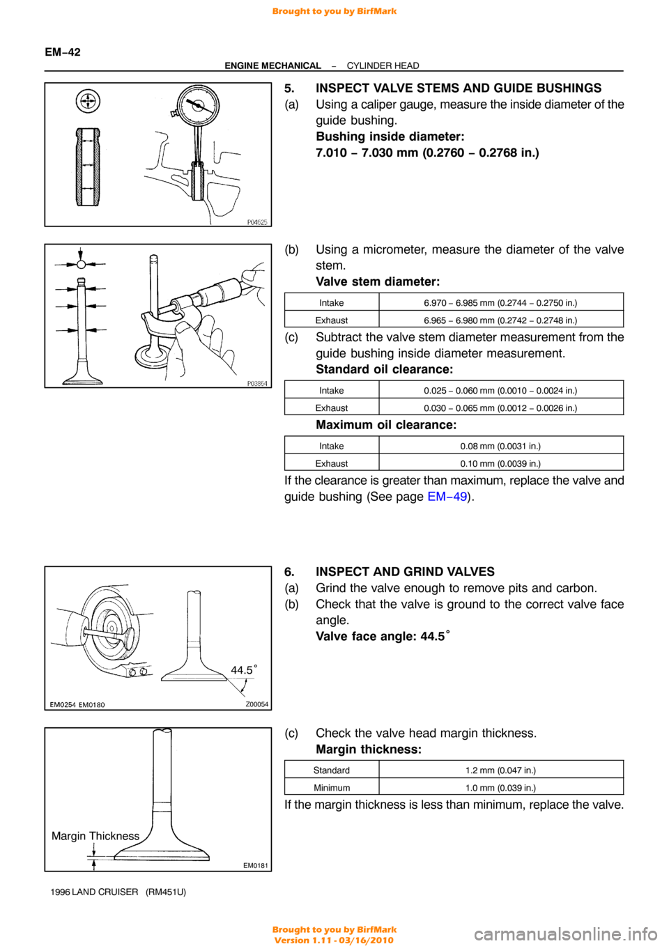
5. INSPECT VALVE STEMS AND GUIDE BUSHINGS
(a) Using a cali per gauge, measure the inside diameter of the
guide bushing.
Bushing inside diameter:
7.010 − 7.030 mm (0.2760 − 0.2768 in.)
(b) Using a micrometer, measure the diameter of the valve stem.
Valve stem diameter:
Intake6.970 − 6.985 mm (0.2744 − 0.2750 in.)
Exhaust6.965 − 6.980 mm (0.2742 − 0.2748 in.)
(c) Subtract the valve stem diameter measurement from the
guide bushing inside diameter measurement.
Standard oil clearance:
Intake0.025 − 0.060 mm (0.0010 − 0.0024 in.)
Exhaust0.030 − 0.065 mm (0.0012 − 0.0026 in.)
Maximum oil clearance:
Intake0.08 mm (0.0031 in.)
Exhaust0.10 mm (0.0039 in.)
If the clearance is greater than maximum, replace the valve and
guide bushing (See page EM−49).
6. INSPECT AND GRIND VALVES
(a) Grind the valve enough to remove pits and carbon.
(b) Check that the valve is ground to the correct valve face angle.
Valve face angle: 44.5°
(c) Check the valve head margin thickness. Margin thickness:
Standard1.2 mm (0.047 in.)
Minimum1.0 mm (0.039 in.)
If the margin thickness is less than minimum, replace the valve.
Brought to you by BirfMark
Brought to you by BirfMark
Version 1.11 - 03/16/2010
Page 830 of 1399

EM0281
P03976
P03977
−
ENGINE MECHANICAL CYLINDER HEAD
EM−45
1996 LAND CRUISER (RM451U)
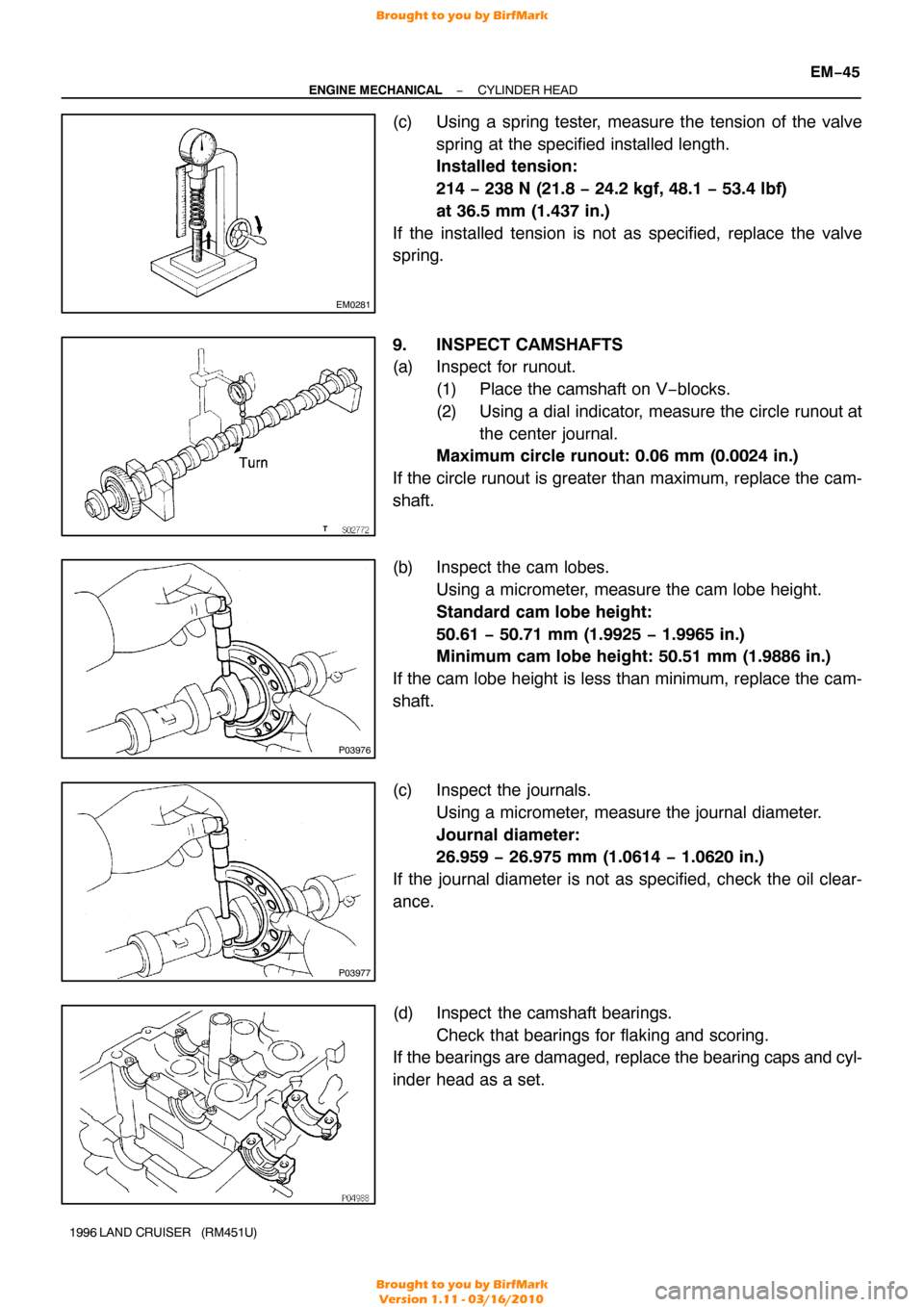
(c) Using a spring tester, measure the tension of the valve
spring at the specified installed length.
Installed tension:
214 − 238 N (21.8 − 24.2 kgf, 48.1 − 53.4 lbf)
at 36.5 mm (1.437 in.)
If the installed tension is not as specified, replace the valve
spring.
9. INSPECT CAMSHAFTS
(a) Inspect for runout. (1) Place the camshaft on V−blocks.
(2) Using a dial indicator, measure the circle runout atthe center journal.
Maximum circle runout: 0.06 mm (0.0024 in.)
If the circle runout is greater than maximum, replace the cam-
shaft.
(b) Inspect the cam lobes. Using a micrometer, measure the cam lobe height.
Standard cam lobe height:
50.61 − 50.71 mm (1.9925 − 1.9965 in.)
Minimum cam lobe height: 50.51 mm (1.9886 in.)
If the cam lobe height is less than minimum, replace the cam-
shaft.
(c) Inspect the journals. Using a micrometer, measure the journal diameter.
Journal diameter:
26.959 − 26.975 mm (1.0614 − 1.0620 in.)
If the journal diameter is not as specified, check the oil clear-
ance.
(d) Inspect the camshaft bearings. Check that bearings for flaking and scoring.
If the bearings are damaged, replace the bearing caps and cyl-
inder head as a set.
Brought to you by BirfMark
Brought to you by BirfMark
Version 1.11 - 03/16/2010
Page 839 of 1399

EM1E7−01
EM−54
−
ENGINE MECHANICAL CYLINDER HEAD
1996 LAND CRUISER (RM451U)
INSTALLATION
1. INSTALL CYLINDER HEAD AND INTAKE MANIFOLD ASSEMBLY
(a) Place the cylinder head on the cylinder head. (1) Apply seal packing to the 2 locations as shown.
Seal packing: Part No. 08826−00080 or equivalent
NOTICE:
Do not apply too much seal packing
(2) Place a new cylinder head gasket in position on the
cylinder block.
NOTICE:
Be careful of the installation direction. (3) Place the cylinder head in position on the cylinderhead gasket.
(b) Install the cylinder head bolts.
HINT:
�The cylinder head bolts are tightened in 3 progressive
steps (steps (b), (d) and (e)).
�If any cylinder head bolt is broken or deformed, replace
it.
(1) Apply a light coat of engine oil on the threads and under the heads of the cylinder head bolts.
(2) Install and uniformly tighten the 14 cylinder head
bolts and plate washers in several passes, in the se-
quence shown.
Torque: 39 N·m (400 kgf·cm, 29 ft·lbf)
If any of the cylinder head bolts does not meet the torque speci-
fication, replace the cylinder head bolt.
(3) Mark the front of the cylinder head bolt head withpaint.
(4) Retighten the cylinder head bolts by 90 ° in the nu-
merical order shown.
(5) Retighten the cylinder head bolts by an additional 90°.
(6) Check that the painted mark is now facing rearward.
Brought to you by BirfMark
Brought to you by BirfMark
Version 1.11 - 03/16/2010
Page 841 of 1399

P22567A16077
2 Dot Marks
EM−56
−
ENGINE MECHANICAL CYLINDER HEAD
1996 LAND CRUISER (RM451U)
(a) Install the intake camshaft.
(1) Apply engine oil to the thrust portion of the intakecamshaft.
(2) Lightly place the intake camshaft on top of the cylin-
der head as shown in the illustration so that the No.
1 and No. 4 cylinder cam lobes face downward.
(3) Lightly push the camshaft towards the front without
applying excessive force.
(4) Place the No. 2 and No. 5 bearing caps in their prop-
er location.
(5) Temporarily tighten these bearing cap bolts uni- formly and alternately in several passes until the
bearing caps are snug with the cylinder head.
(6) Place the No. 3, No. 4, No. 6 and No. 7 bearing caps
in their proper location.
(7) Temporarily tighten these bearing cap bolts, alter- nately tightening the left and right bolts uniformly.
(8) Place the No. 1 bearing cap in its proper location. When doing this, check that there is no gap be-
tween the cylinder head and the contact surface of
bearing cap.
(9) Temporarily tighten the bearing cap bolts, alternate-
ly tightening the left and right bolts uniformly.
(10) Uniformly tighten the 14 bearing cap bolts in several
passes.
Torque: 16 N·m (160 kgf·cm, 12 ft·lbf)
(b) Install the exhaust camshaft. (1) Set the timing mark (2 dot marks) of the camshaftdrive gear at approx. 35 ° angle by turning the hexa-
gon wrench head portion of the intake camshaft
with a wrench.
Brought to you by BirfMark
Brought to you by BirfMark
Version 1.11 - 03/16/2010
Page 842 of 1399

−
ENGINE MECHANICAL CYLINDER HEAD
EM−57
1996 LAND CRUISER (RM451U)
(2) Apply engine oil to thrust portion of the exhaust
camshaft.
(3) Engage the exhaust camshaft gear to the intake
camshaft gear by matching the timing marks (two
dot marks) on each gear.
(4) Roll down the exhaust camshaft onto the bearing journals while engaging gears with each other.
(5) Lightly push the intake camshaft towards the front without applying excessive force.
(6) Install the No. 4 and No. 6 bearing caps in their proper location.
(7) Temporarily tighten the bearing cap bolts uniformly and alternately in several passes until the bearing
caps are snug with the cylinder head.
(8) Place the No. 2, No. 3, No. 5 and No. 7 bearing caps
in their proper location.
(9) Temporarily tighten these bearing cap bolts, alter- nately tightening the left and right bolts uniformly.
(10) Place the No. 1 bearing cap in its proper location. When doing this, check that there is no gap be-
tween the cylinder head and the contact surface of
bearing cap.
(11) Temporarily tighten the bearing cap bolts, alternate-
ly tightening the left and right bolts uniformly.
(12) Uniformly tighten the 14 bearing cap bolts in several
passes.
Torque: 16 N·m (160 kgf·cm, 12 ft·lbf)
(13) Bring the service bolt installed in the driven sub −
gear upward by turning the hexagon wrench head
portion of the camshaft with a wrench.
(14) Remove the service bolt.
(15) Check that the intake and exhaust camshafts turn smoothly.
Brought to you by BirfMark
Brought to you by BirfMark
Version 1.11 - 03/16/2010
Page 861 of 1399

EM1EE−02
EM−76
−
ENGINE MECHANICAL ENGINE UNIT
1996 LAND CRUISER (RM451U)
INSTALLATION
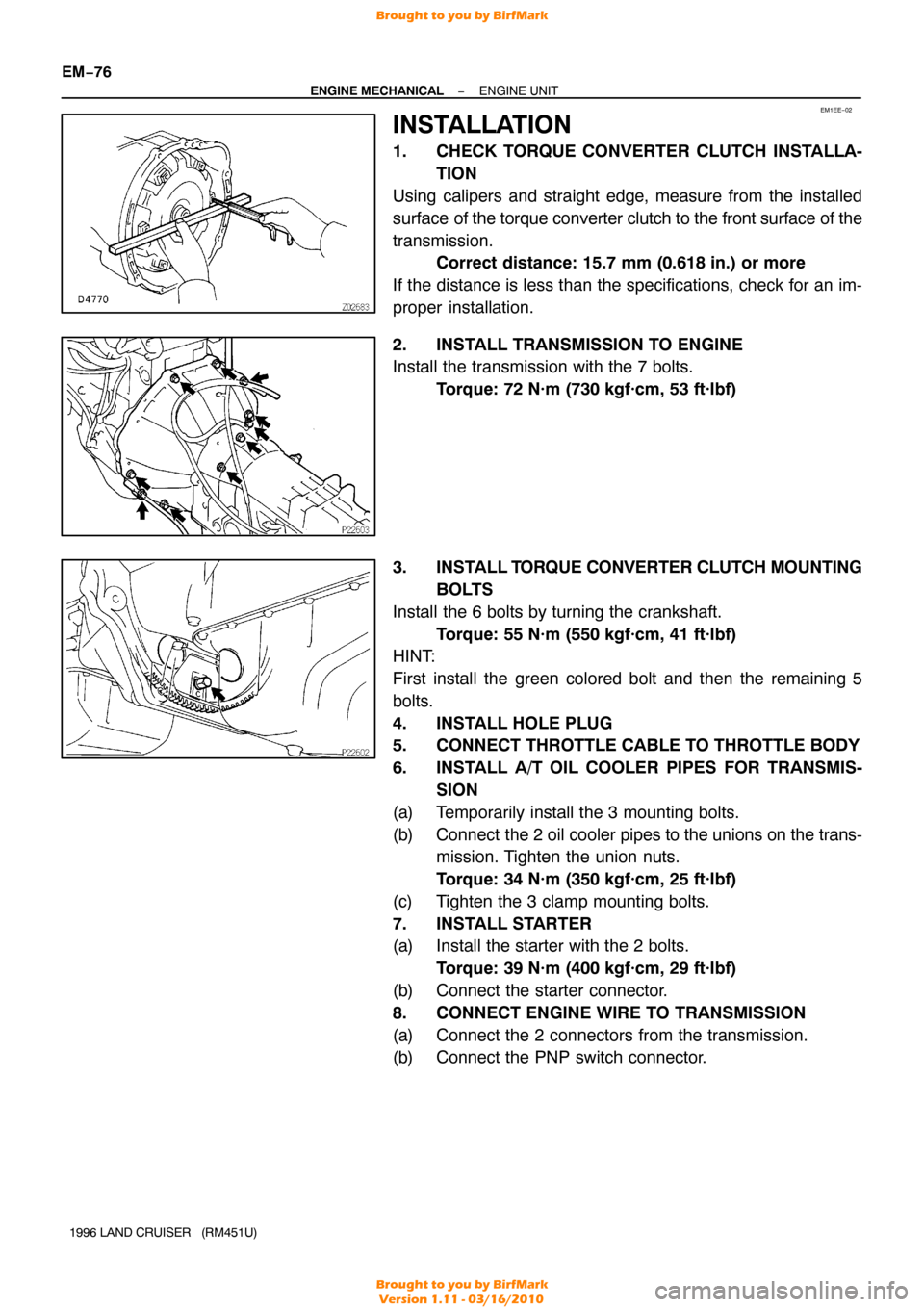
1. CHECK TORQUE CONVERTER CLUTCH INSTALLA- TION
Using calipers and straight edge, measure from the installed
surface of the torque converter clutch to the front surface of the
transmission. Correct distance: 15.7 mm (0.618 in.) or more
If the distance is less than the specifications, check for an im-
proper installation.
2. INSTALL TRANSMISSION TO ENGINE
Install the transmission with the 7 bolts. Torque: 72 N·m (730 kgf·cm, 53 ft·lbf)
3. INSTALL T ORQUE CONVERTER CLUTCH MOUNTING
BOLTS
Install the 6 bolts by turning the crankshaft. Torque: 55 N·m (550 kgf·cm, 41 ft·lbf)
HINT:
First install the green colored bolt and then the remaining 5
bolts.
4. INSTALL HOLE PLUG
5. CONNECT THROTTLE CABLE TO THROTTLE BODY
6. INSTALL A/T OIL COOLER PIPES FOR TRANSMIS-
SION
(a) Temporarily install the 3 mounting bolts.
(b) Connect the 2 oil cooler pipes to the unions on the trans-
mission. Tighten the union nuts.
Torque: 34 N·m (350 kgf·cm, 25 ft·lbf)
(c) Tighten the 3 clamp mounting bolts.
7. INSTALL STARTER
(a) Install the starter with the 2 bolts. Torque: 39 N·m (400 kgf·cm, 29 ft·lbf)
(b) Connect the starter connector.
8. CONNECT ENGINE WIRE TO TRANSMISSION
(a) Connect the 2 connectors from the transmission.
(b) Connect the PNP switch connector.
Brought to you by BirfMark
Brought to you by BirfMark
Version 1.11 - 03/16/2010
Page 866 of 1399

−
ENGINE MECHANICAL ENGINE UNIT
EM−81
1996 LAND CRUISER (RM451U)
26. CONNECT EVAP HOSE
27. CONNECT BRAKE BOOSTER VACUUM HOSE
28. CONNECT HEATER VALVE AND ENGINE WIRE TO
COWL PANEL
(a) Connect the heater valve with the 2 bolts.
(b) Connect the engine wire and ground strap with the 2 bolts.
29. CONNECT HEATER HOSES
30. CONNECT ACCELERATOR CABLE TO THROTTLE BODY
31. CONNECT CRUISE CONTROL ACTUATOR CABLE TO
THROTTLE BODY
32. INSTALL AIR CLEANER CASE
33. INSTALL AIR CLEANER HOSE AND CAP
34. CONNECT OIL COOLER HOSE TO OIL COOLER PIPE
35. INSTALL RADIATOR (See page CO−16)
36. INSTALL RADIATOR GRILLE
Install the radiator grille with the 5 screws and clip.
37. INSTALL BATTERY TRAY AND BATTERY
(a) Install the battery tray with the 5 bolts.
(b) Connect the ground strap with the bolt.
(c) Install the battery and hold−down clamp with the nuts.
(d) Connect the battery cables.
38. FILL WITH ENGINE OIL
39. FILL RADIATOR WITH ENGINE COOLANT
40. START ENGINE AND CHECK FOR LEAKS
41. CHECK AUTOMATIC TRANSMISSION FLUID LEVEL
42. CHECK IGNITION TIMING (See page EM−10)
43. INSTALL HOOD
44. PERFORM ROAD TEST
Check for abnormal noise, shock, slippage, correct shift points
and smooth operation.
45. RECHECK ENGINE COOLANT AND ENGINE OIL LEV-
ELS
Brought to you by BirfMark
Brought to you by BirfMark
Version 1.11 - 03/16/2010
Page 869 of 1399
EM−84
−
ENGINE MECHANICAL CYLINDER BLOCK
1996 LAND CRUISER (RM451U)
9. REMOVE RH ENGINE MOUNTING BRACKET
(a) Remove the nut and insulator.
(b) Remove the 4 bolts and bracket.
10. REMOVE LH ENGINE MOUNTING BRACKET
(a) Remove the nut and insulator.
(b) Remove the 4 bolts and bracket.
11. REMOVE OIL COOLER COVER AND OIL COOLER
Remove the 10 bolts, 2 nuts, oil cooler cover with the oil cooler
and gasket.
12. REMOVE REAR OIL SEAL RETAINER
Remove the 4 bolts and retainer.
13. CHECK CONNECTING ROD THRUST CLEARANCE
Using a dial indicator, measure the thrust clearance while mov-
ing the connecting rod back and forth.
Standard thrust clearance:
0.160 − 0.262 mm (0.0063 − 0.0103 in.)
Maximum thrust clearance: 0.362 mm (0.0143 in.)
If the thrust clearance is greater than maximum, replace the
connecting rod assembly. If necessary , replace the crankshaft.
Brought to you by BirfMark
Brought to you by BirfMark
Version 1.11 - 03/16/2010