Page 346 of 1399
BR1CL-01
-
BRAKE BRAKE MASTER CYLINDER
BR-13
1996 LAND CRUISER (RM451U)
REASSEMBLY
Reassembly is in the reverse order of disassembly.
NOTICE:
Apply lithium soap base glycol grease to the rubber parts indicated by t\
he arrows
(See page BR-9 ).
Brought to you by BirfMark
Brought to you by BirfMark
Version 1.11 - 03/16/2010
Page 347 of 1399
BR1CM-01
BR-14
-
BRAKE BRAKE MASTER CYLINDER
1996 LAND CRUISER (RM451U)
INSTALLATION
Installation is in the reverse order of removal (See page BR-9).
HINT:
�Before installation, adjust length of brake booster push rod (See page \
BR-18).
�After installation, fill brake reservoir with brake fluid, bleed brake s\
ystem (See page BR-4).
�Check for leaks, check and adjust brake pedal (See page BR-6).
Brought to you by BirfMark
Brought to you by BirfMark
Version 1.11 - 03/16/2010
Page 348 of 1399
BR1CN-01
BR2238
-
BRAKE BRAKE BOOSTER ASSEMBLY
BR-15
1996 LAND CRUISER (RM451U)
BRAKE BOOSTER ASSEMBLY
OPERATION
1. OPERATING CHECK
(a) Depress the brake pedal several times with the engine off
and check that there is no change in the pedal reserve
distance.
(b) Depress the brake pedal and start the engine. If the pedal
goes down slightly, operation is normal.
2. AIR TIGHTNESS CHECK
(a) Start the engine and stop it after 1 or 2 minutes. Depress the brake pedal several times slowly. If the pedal goes
down furthest the 1st time, but gradually rises after the
2nd or 3rd time, the booster is air tight.
(b) Depress the brake pedal while the engine is running, and
stop the engine with the pedal depressed. If there is no
change in the pedal reserve travel after holding the pedal
for 30 seconds, the booster is air tight.
Brought to you by BirfMark
Brought to you by BirfMark
Version 1.11 - 03/16/2010
Page 349 of 1399
BR1CO-01
BR-16
-
BRAKE BRAKE BOOSTER ASSEMBLY
1996 LAND CRUISER (RM451U)
COMPONENTS
Brought to you by BirfMark
Brought to you by BirfMark
Version 1.11 - 03/16/2010
Page 350 of 1399
BR2237
BR1NM−01
BR2238
−
BRAKE BRAKE BOOSTER ASSEMBLY
BR−17
999
Author�: Date�:
1996 LAND CRUISER (RM451U)
BRAKE BOOSTER ASSEMBLY
OPERATION
1. OPERATING CHECK
(a) Depress the brake pedal several times with the engine off
and check that there is no change in the pedal reserve
distance.
(b) Depress the brake pedal and start the engine. If the pedal
goes down slightly, operation is normal.
2. AIR TIGHTNESS CHECK
(a) Start the engine and stop it after 1 or 2 minutes. Depress
the brake pedal several times slowly. If the pedal goes
down furthest the 1st time, but gradually rises after the
2nd or 3rd time, the booster is air tight.
(b) Depress the brake pedal while the engine is running, and
stop the engine with the pedal depressed. If there is no
change in the pedal reserve travel after holding the pedal
for 30 seconds, the booster is air tight.
Brought to you by BirfMark
Brought to you by BirfMark
Version 1.11 - 03/16/2010
Page 351 of 1399
BR1CO−02
BR−18
−
BRAKE BRAKE BOOSTER ASSEMBLY
1996 LAND CRUISER (RM451U)
COMPONENTS
Brought to you by BirfMark
Brought to you by BirfMark
Version 1.11 - 03/16/2010
Page 352 of 1399
BR1CP−03
BR3753
−
BRAKE BRAKE BOOSTER ASSEMBLY
BR−19
1996 LAND CRUISER (RM451U)
REMOVAL
1. REMOVE MASTER CYLINDER (See page BR−9 )
2. REMOVE THESE PARTS:
�Return spring
�Clip and clevis pin
�Clevis
�Vacuum hose
3. REMOVE BRAKE BOOSTER
(a) Remove the 4 booster installation nuts.
(b) Remove the booster and gasket.
Brought to you by BirfMark
Brought to you by BirfMark
Version 1.11 - 03/16/2010
Page 353 of 1399

BR1CQ−01
BR3976
SST
Gasket
R11347
SST
BR−20
−
BRAKE BRAKE BOOSTER ASSEMBLY
1996 LAND CRUISER (RM451U)
INSTALLATION
1. INSTALL BRAKE BOOSTER
(a) Install the booster and a new gasket.
(b) Install the clevis to the operating rod.
(c) Install and torque the booster installation nuts. Torque: 13 N·m (130 kgf·cm, 9 ft·lbf)
(d) Install the clevis pin into the clevis and brake pedal, and
install the clip to the clevis pin.
(e) Install the pedal return spring.
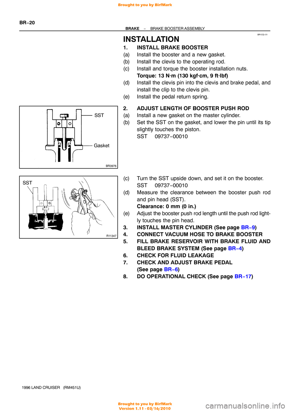
2. ADJUST LENGTH OF BOOSTER PUSH ROD
(a) Install a new gasket on the master cylinder.
(b) Set the SST on the gasket, and lower the pin until its tip slightly touches the piston.
SST 09737−00010
(c) Turn the SST upside down, and set it on the booster. SST 09737−00010
(d) Measure the clearance between the booster push rod and pin head (SST).
Clearance: 0 mm (0 in.)
(e) Adjust the booster push rod length until the push rod light-
ly touches the pin head.
3. INSTALL MASTER CYLINDER (See page BR−9 )
4. CONNECT VACUUM HOSE TO BRAKE BOOSTER
5. FILL BRAKE RESERVOIR WITH BRAKE FLUID AND
BLEED BRAKE SYSTEM (See page BR−4 )
6. CHECK FOR FLUID LEAKAGE
7. CHECK AND ADJUST BRAKE PEDAL (See page BR−6 )
8. DO OPERATIONAL CHECK (See page BR−17 )
Brought to you by BirfMark
Brought to you by BirfMark
Version 1.11 - 03/16/2010