Page 940 of 1399

P22572
P22574B13834
Drain Plug
Drain Plug
MA0621B13835
Lubricating Positions: 1. Spider2. Slide Yoke1
2 1
MA−8
−
MAINTENANCE CHASSIS
48
Author�: Date�:
1996 LAND CRUISER (RM451U)
7. REPLACE TRANSFER AND DIFFERENTIAL OIL
(a) Remove the drain plug and drain the oil.
(b) Reinstall the drain plug securely.
(c) Add new oil until it begins to run out of the filler hole.
Oil drade and viscosity: See step 5.
Oil capacity:
Transfer oil
1.7 liters (1.8 US qts, 1.5 lmp. qts)
Front differential oil (w/o Differential lock)
2.8 liters (3.0 US qts, 2.5 lmp. qts)
Front differential oil (w/ Differential lock)
2.65 liters (2.8 US qts, 2.3 lmp. qts)
Rear differential oil
3.25 liters (3.4 US qts, 2.9 lmp. qts)
8. REPACK FRONT WHEEL BEARINGS (See pages SA−7 and SA−9 )
9. LUBE STEERING KNUCKLE CHASSIS AND PROPEL-
LER SHAFT
(a) Remove the screw plug from each steering knuckle and repack with lubricant.
Steering knuckle grease:
Molybdenum disulfide lithium base chassis grease
(NLGI No. 2)
(b) Reinstall the 2 screw plugs.
(c) Lubricate chassis components, referring to the lubrication
chart. Before pumping in grease, wipe off any mud and
dust on the grease fitting.
Grease grade:
Lithium base chassis grease (NLGI No. 2)
Brought to you by BirfMark
Brought to you by BirfMark
Version 1.11 - 03/16/2010
Page 941 of 1399

MA04W−01
−
MAINTENANCE BODY
MA−9
49
Author�: Date�:
1996 LAND CRUISER (RM451U)
BODY
INSPECTION
1. TIGHTEN BOLTS AND NUTS ON CHASSIS AND BODY
(a) Tighten the front seat−to−body mounting bolts. Torque: 39 N·m (400 kgf·cm, 29 ft·lbf)
(b) Under Severe Conditions: In addition to the above maintenance items, check for
loose or missing nuts and bolts on the steering system,
drive train, suspension system, fuel tank mounts, engine
mounts, etc.
2. FINAL INSPECTION
(a) Check the operation of the body parts:
�Hood:
Auxiliary catch operates properly
Hood locks securely when closed
�Front and rear doors:
Door locks operate properly
Doors close properly
�Back door:
Door lock operates properly
�Seats:
Seat adjusts easily and locks securely in any posi-
tion
Front seat back locks securely in any position
Folding −down rear seat backs look securely
(b) Road test
�Check the engine and chassis for abnormal noises.
�Check that the vehicle does not wander or pull to
one side.
�Check that the brakes work properly and do not
drag.
(c) Be sure to deliver a clean car. Especially check the steering wheel, shift lever knob, all
switch knobs, door handles and seats.
Brought to you by BirfMark
Brought to you by BirfMark
Version 1.11 - 03/16/2010
Page 1057 of 1399
RS0PE−01
−
SUPPLEMENTAL RESTRAINT SYSTEM AIRBAG SENSOR ASSEMBLY
RS−33
1996 LAND CRUISER (RM451U)
REMOVAL
NOTICE:
Do not open the cover or the case of the ECU and various
computers unless absolutely necessary.
(If the IC terminals are touched, the IC may be destroyed by
static electricity.)
1. REMOVE THESE PARTS:
(a) Transfer shirt knob
(b) Front console box
2. REMOVE AIRBAG SENSOR ASSEMBLY
(a) Disconnect the connector.
NOTICE:
Remove the connector with the sensor assembly installed.
(b) Using a torx wrench remove the 4 screws and the airbag sensor assembly.
Torx wrench: T40 (Part No. 09042 −00020 or locally
manufactured tool)
Brought to you by BirfMark
Brought to you by BirfMark
Version 1.11 - 03/16/2010
Page 1065 of 1399

SA−2
−
SUSPENSION AND AXLE TROUBLESHOOTING
859
Author�: Date�:
1996 LAND CRUISER (RM451U)
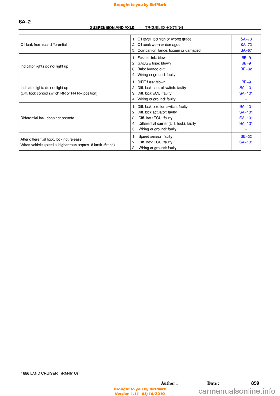
Oil leak from rear dif
ferential
1. Oil level: too high or wrong grade
2. Oil seal: worn or damaged
3. Companion flange: loosen or damagedSA−73
SA−73
SA−87
Indicator lights do not light up
1. Fusible link: blown
2. GAUGE fuse: blown
3. Bulb: burned out
4. Wiring or ground: faultyBE−9
BE−9
BE−32 −
Indicator lights do not light up
(Diff. lock control switch RR or FR RR position)
1. DIFF fuse: blown
2. Diff. lock control switch: faulty
3. Diff. lock ECU: faulty
4. Wiring or ground: faultyBE−9
SA−101
SA−101 −
Differential lock does not operate
1. Diff. lock position switch: faulty
2. Diff. lock actuator: faulty
3. Diff. lock ECU: faulty
4. Differential carrier (Diff. lock): faulty
5. Wiring or ground: faultySA−101
SA−101
SA−101
SA−101−
After differential lock, lock not release
When vehicle speed is higher than approx. 8 km/h (5mph)1. Speed sensor: faulty
2. Diff. lock ECU: faulty
3. Wiring or ground: faultyBE−32
SA−101 −
Brought to you by BirfMark
Brought to you by BirfMark
Version 1.11 - 03/16/2010
Page 1073 of 1399
R08416
SA−10
−
SUSPENSION AND AXLE FRONT AXLE HUB
1996 LAND CRUISER (RM451U)
(e) Secure the lock nut by bending one of the lock washer
teeth inward and the other lock washer teeth outward.
7. INSTALL FLANGE
(a) Place a new gasket in position on the axle hub.
(b) Apply MP grease to the inner flange splines.
(c) Install the flange to the axle hub.
(d) Install the 6 cone washers, plate washers and nuts.
(e) Torque the 6 nuts.
Torque: 35 N·m (360 kgf·cm, 26 ft·lbf)
(f) Install the bolt in the axle shaft and pull it out.
(g) Using a snap ring expander, install a new snap ring.
(h) Remove the bolt.
(i) Coat inside of the cap with MP grease.
(j) Install the cap to the flange.
8. INSTALL BRAKE CALIPER (See page BR−29 )
9. INSTALL FRONT WHEEL Torque:
Steel wheel: 147 N·m (1,500 kgf·cm, 109 ft·lbf)
Alumimum wheel: 103 N·m (1,050 kgf·cm, 76 ft·lbf)
10. BLEED BRAKE LINE
Brought to you by BirfMark
Brought to you by BirfMark
Version 1.11 - 03/16/2010
Page 1081 of 1399

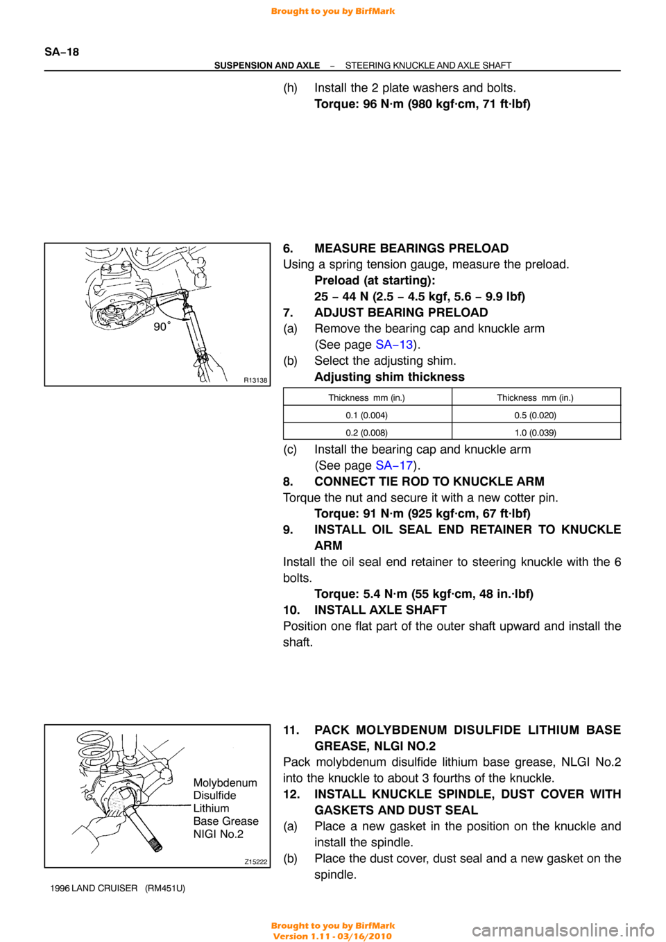
R13138
90°
Z15222
Molybdenum
Disulfide
Lithium
Base Grease
NIGI No.2
SA−18
−
SUSPENSION AND AXLE STEERING KNUCKLE AND AXLE SHAFT
1996 LAND CRUISER (RM451U)
(h) Install the 2 plate washers and bolts.
Torque: 96 N·m (980 kgf·cm, 71 ft·lbf)
6. MEASURE BEARINGS PRELOAD
Using a spring tension gauge, measure the preload. Preload (at starting):
25 − 44 N (2.5 − 4.5 kgf, 5.6 − 9.9 lbf)
7. ADJUST BEARING PRELOAD
(a) Remove the bearing cap and knuckle arm (See page SA−13 ).
(b) Select the adjusting shim. Adjusting shim thickness
Thickness mm (in.)Thickness mm (in.)
0.1 (0.004)0.5 (0.020)
0.2 (0.008)1.0 (0.039)
(c) Install the bearing cap and knuckle arm (See page SA−17 ).
8. CONNECT TIE ROD TO KNUCKLE ARM
Torque the nut and secure it with a new cotter pin. Torque: 91 N·m (925 kgf·cm, 67 ft·lbf)
9. INSTALL OIL SEAL END RETAINER TO KNUCKLE ARM
Install the oil seal end retainer to steering knuckle with the 6
bolts. Torque: 5.4 N·m (55 kgf·cm, 48 in.·lbf)
10. INSTALL AXLE SHAFT
Position one flat part of the outer shaft upward and install the
shaft.
11. PACK MOLYBDENUM DISULFIDE LITHIUM BASE GREASE, NLGI NO.2
Pack molybdenum disulfide lithium base grease, NLGI No.2
into the knuckle to about 3 fourths of the knuckle.
12. INSTALL KNUCKLE SPINDLE, DUST COVER WITH
GASKETS AND DUST SEAL
(a) Place a new gasket in the position on the knuckle and
install the spindle.
(b) Place the dust cover, dust seal and a new gasket on the spindle.
Brought to you by BirfMark
Brought to you by BirfMark
Version 1.11 - 03/16/2010
Page 1165 of 1399

Z07254
M3 M4 M1 M2
Z07255
Wire Harness Side
SA−102
−
SUSPENSION AND AXLE DIFFERENTIAL LOCKING SYSTEM
959
Author�: Date�:
1996 LAND CRUISER (RM451U)
(6) Check the voltage between the terminals of the Diff.
lock ECU when switching the Diff. lock control
switch with the speedometer, registering approx. 8
km/h (5 mph) or more.
(7) Check that the indicator lights blink when center Diff. lock release mode is set.
Diff. lock is released for both the front wheels and
rear wheels at this time.
(8) Return the Diff. lock control switch to OFF.
(9) Stop the engine and lower the vehicle.
2. INSPECT DIFF. LOCK SYSTEM CIRCUIT
(a) Inspect the system circuit with connector disconnected. Disconnect the connector from the Diff. lock ECU and in-
spect the connector on the wire harness side, as shown
in the chart.
Trouble Part/
Terminals (Symbols)ConditionSpecified V alue
Rear diff. lock actuator/
1 (M2) − 3 (M1)−Less than 100 Ω
Front diff. lock actuator/
5 (M4) − 7 (M1)−Less than 100 Ω
Body ground/
13 (GND) − Body ground−Continuity
Vehicle speed sensor/
4(SPD) − Body groundVehicle moving slowly1 pulse each 40 cm (15.75 in.)
Brought to you by BirfMark
Brought to you by BirfMark
Version 1.11 - 03/16/2010
Page 1166 of 1399

Z07256
ECU Side
−
SUSPENSION AND AXLE DIFFERENTIAL LOCKING SYSTEM
SA−103
960
Author�: Date�:
1996 LAND CRUISER (RM451U) DIFF. fuse/
8 (IG) − Body ground
Ignition switch ONBattery positive voltage
Rear diff. lock position switch/
2 (RLP) − Body groundIgnition switch ON,
Indicator light (Rear) ONAbout 0 V
Ignition switch ON,
Indicator light (Rear) OFFBattery positive voltage
Front diff. lock position switch/ 9 (FLP) − Body ground
Ignition switch ON,
Indicator light (front) ON.About 0 V
Ignition switch ON,
Indicator light (front) OFFBattery positive voltage
Center diff. indicator switch/ 15 (4WD) − Body groud
Ignition switch ON,
Indicator light (Center diff. lock) ONAbout 0 V
Ignition switch ON,
Indicator light (Ce nter diff. lock) OFFBattery positive voltage
Differential lock control switch/
12 (R) − Body ground
Ignition switch ON,
Diff. lock control switch RR or FR RRBattery positive voltage
Ignition switch ON,
Diff. lock control switch OFFAbout 0 V
Differential lock control switch/ 6 (RF) − Body ground
Ignition switch ON,
Diff. lock control switch FR RRBattery positive voltage
Ignition switch ON,
Diff. lock control switch OFF or RRAbout 0 V
HINT:
When a signal enters the ECU to LOCK the front dif ferential and
set the rear differential to FREE (when battery positive voltage
is inputted to terminal 6 (RF) of ECU and about 0 V is inputted
to terminal 12 (R)), or a signal to FREE both the front and rear
differentials, the indicator lights keep blinking until the ignition
switch is turned off (Fail−safe function).
If the circuit is not as specified, check and repair or replace the
trouble part shown in the table above.
(b) Inspect the battery positive voltage Battery positive voltage: 10 − 14.5 V
(c) Inspect the system circuit with connector connected (1) Turn the ignition switch to the ON position.
(2) Keep the center Diff. lock condition.
(3) Remove the Diff. lock ECU.
(4) Using a voltmeter, measure the voltage when thedifferential lock control switch is in the position, as
shown below.
Terminals (Symbols)Switch PositionSTD Voltage (V)
15 (4WD) − 13 (GND)−0.5 or less
9 (FLP) − 13 (GND)FR RR0.5 or less
2 (RLP) − 13 (GND)RR or FR RR0.5 or less
Brought to you by BirfMark
Brought to you by BirfMark
Version 1.11 - 03/16/2010