Page 1076 of 1399

SA1UG−01
W00495
SA2644
SST
R08383
R13137
−
SUSPENSION AND AXLE STEERING KNUCKLE AND AXLE SHAFT
SA−13
1996 LAND CRUISER (RM451U)
REMOVAL
1. REMOVE FRONT AXLE HUB (See page SA−7 )
2. REMOVE ABS SPEED SENSOR
Remove the 2 bolts and disconnect the speed sensor from the
steering knuckle.
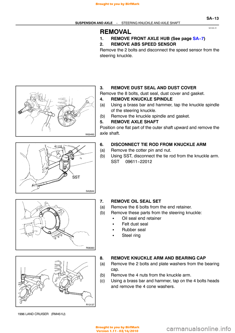
3. REMOVE DUST SEAL AND DUST COVER
Remove the 8 bolts, dust seal, dust cover and gasket.
4. REMOVE KNUCKLE SPINDLE
(a) Using a brass bar and hammer, tap the knuckle spindle of the steering knuckle.
(b) Remove the knuckle spindle and gasket.
5. REMOVE AXLE SHAFT
Position one flat part of the outer shaft upward and remove the
axle shaft.
6. DISCONNECT TIE ROD FROM KNUCKLE ARM
(a) Remove the cotter pin and nut.
(b) Using SST, disconnect the tie rod from the knuckle arm. SST 09611 −22012
7. REMOVE OIL SEAL SET
(a) Remove the 6 bolts from the end retainer.
(b) Remove these parts from the steering knuckle:
�Oil seal end retainer
�Felt dust seal
�Rubber seal
�Steel ring
8. REMOVE KNUCKLE ARM AND BEARING CAP
(a) Remove the 2 bolts and plate washers from the bearing cap.
(b) Remove the 4 nuts from the knuckle arm.
(c) Using a brass bar and hammer, tap on the 4 bolts heads and remove the 4 cone washers.
Brought to you by BirfMark
Brought to you by BirfMark
Version 1.11 - 03/16/2010
Page 1077 of 1399
Q07149SST
SA−14
−
SUSPENSION AND AXLE STEERING KNUCKLE AND AXLE SHAFT
1996 LAND CRUISER (RM451U)
(d) Using SST, remove the bearing cap and shim from the
steering knuckle.
SST 09606−60020
HINT:
�Use the SST without a collar.
�In some cases, to satisfy the standard value of preload,
more than one shims are used.
(e) Using SST, remove the knuckle arm and shim from the steering knuckle.
SST 09606−60020
HINT:
�Use the SST without a collar.
�In some cases, to satisfy the standard value of preload,
more than one shims are used.
9. REMOVE STEERING KNUCKLE AND BEARING
HINT:
Mark the removed adjusting shim and bearings so as to enable
reassembling them to their proper positions.
10. REMOVE OIL SEAL TO AXLE HOUSING
Using SST, remove the oil seal. SST 09308−00010
Brought to you by BirfMark
Brought to you by BirfMark
Version 1.11 - 03/16/2010
Page 1078 of 1399

SA1UH−01
R08435
SSTSST
Z06889
FA0203
−
SUSPENSION AND AXLE STEERING KNUCKLE AND AXLE SHAFT
SA−15
1996 LAND CRUISER (RM451U)
REPLACEMENT
1. INSPECT KNUCKLE SPINDLE
Clean the knuckle spindle and inspect the bushing for wear or
damage.
2. REPLACE BUSHING
(a) Using SST, remove the bushing.
SST 09612−65014 (09612 −01010, 09612−01050)
(b) Using SST and a press, install a new bushing into the spindle.
SST 09618−60010
3. INSPECT BEARING
Clean the bearing and 2 outer races and inspect them for wear
or damage.
4. IF NECESSARY, REPLACE BEARING OUTER RACE
(a) Using a brass bar and hammer, remove the bearing outer
race.
(b) Using SST and a hammer, carefully install a new bearing outer race.
SST 09605−60010
5. INSPECT BIRFIELD JOINT INNER PARTS
(a) Hold the inner shaft in a vise.
(b) Place a brass bar against the joint inner race and remove the outer shaft.
(c) Tilt the inner race and cage and take out the bearing balls one by one.
(d) Fit the 2 large openings in the cage against the protruding parts of the outer shaft and remove the cage and inner
race.
(e) Remove the inner race from the cage though the large opening.
(f) Clean and inspect the joint parts for wear or damage.
Brought to you by BirfMark
Brought to you by BirfMark
Version 1.11 - 03/16/2010
Page 1079 of 1399

FA0107
SA−16
−
SUSPENSION AND AXLE STEERING KNUCKLE AND AXLE SHAFT
1996 LAND CRUISER (RM451U)
(g) Coat the joint inner parts and outer shaft inside with mo-
lybdenum disulpfide lithium base grease, NLGI No.2.
(h) Install the inner race in the cage through the large open-
ing.
(i) Position the protruding end of the inner race toward the wide side of the cage.
(j) Assemble the cage and inner race to the outer shaft by
fitting the 2 large openings in the cage against the pro-
truding parts of the outer shaft.
(k) Make sure to position the wide side of the cage and the inner race protruding end outward.
(l) Fit in the inner race and cage and install the 6 bearing balls in the outer shaft (See step (c)).
(m) Pack molybdenum disulpfide lithium base grease, NLGI No.2 in the outer shaft.
(n) Install a new snap ring on the inner shaft.
(o) Hold the outer shaft in a vise and while compressing the snap ring, install the inner shaft to the outer shaft.
(p) Make sure that the inner shaft cannot be pulled out.
Brought to you by BirfMark
Brought to you by BirfMark
Version 1.11 - 03/16/2010
Page 1080 of 1399

SA1UI−01
SA2650
SST
Z15221
Lithium Base Wheel Bearing
Grease, NIGI No.2
R08387SST
R08388
SST
−
SUSPENSION AND AXLE STEERING KNUCKLE AND AXLE SHAFT
SA−17
1996 LAND CRUISER (RM451U)
INSTALLATION
1. INSTALL OIL SEAL TO AXLE HOUSING
Using SST and a hammer, install a new oil seal into the axle
housing.
SST 09618−60010
2. INSTALL OIL SEAL SET
Install these parts to the steering knuckle:
�Oil seal and retainer
�Felt dust seal
�Rubber seal and steel ring
3. PACK BEARINGS WITH LITHIUM BASE WHEEL
BEARING GREASE, NLGI NO.2
(a) Place lithium base wheel bearing grease, NLGI No.2 on your hand.
(b) Pack grease into the bearing until the grease oozes out from the outer side.
(c) Do the same around the bearing circumference.
4. INSTALL STEERING KNUCKLE AND BEARINGS
(a) Place the bearings in positions on the knuckle and axle housing.
(b) Install the knuckle on the axle housing.
5. INSTALL KNUCKLE ARM AND BEARING CAP
(a) Using SST, support the upper bearing inner race. SST 09606−60020
HINT:
Use the SST with a collar.
(b) Install the bearing cap over the shim that were originally
used.
(c) Using a hammer, install the bearing cap into the bearing
inner race.
(d) Using SST, support the lower bearing inner race. SST 09606−60020
HINT:
Use the SST with a collar.
(e) Using a hammer, tap the knuckle arm and shim into the
bearing inner race.
(f) Remove the SST from the knuckle.
(g) Install the 4 cone washers and nuts.
Torque: 96 N·m (980 kgf·cm, 71 ft·lbf)
Brought to you by BirfMark
Brought to you by BirfMark
Version 1.11 - 03/16/2010
Page 1081 of 1399

R13138
90°
Z15222
Molybdenum
Disulfide
Lithium
Base Grease
NIGI No.2
SA−18
−
SUSPENSION AND AXLE STEERING KNUCKLE AND AXLE SHAFT
1996 LAND CRUISER (RM451U)
(h) Install the 2 plate washers and bolts.
Torque: 96 N·m (980 kgf·cm, 71 ft·lbf)
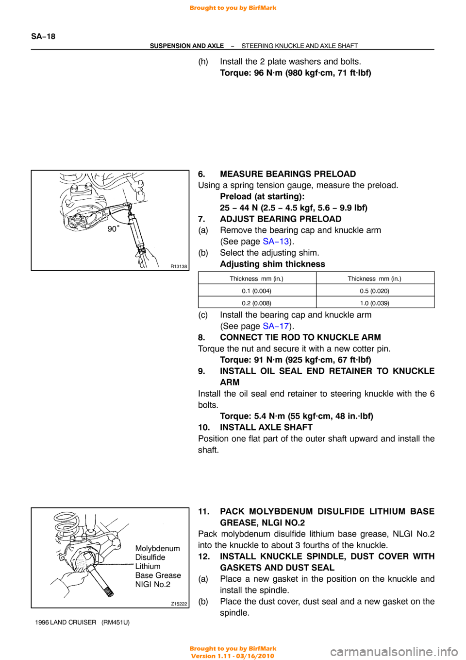
6. MEASURE BEARINGS PRELOAD
Using a spring tension gauge, measure the preload. Preload (at starting):
25 − 44 N (2.5 − 4.5 kgf, 5.6 − 9.9 lbf)
7. ADJUST BEARING PRELOAD
(a) Remove the bearing cap and knuckle arm (See page SA−13 ).
(b) Select the adjusting shim. Adjusting shim thickness
Thickness mm (in.)Thickness mm (in.)
0.1 (0.004)0.5 (0.020)
0.2 (0.008)1.0 (0.039)
(c) Install the bearing cap and knuckle arm (See page SA−17 ).
8. CONNECT TIE ROD TO KNUCKLE ARM
Torque the nut and secure it with a new cotter pin. Torque: 91 N·m (925 kgf·cm, 67 ft·lbf)
9. INSTALL OIL SEAL END RETAINER TO KNUCKLE ARM
Install the oil seal end retainer to steering knuckle with the 6
bolts. Torque: 5.4 N·m (55 kgf·cm, 48 in.·lbf)
10. INSTALL AXLE SHAFT
Position one flat part of the outer shaft upward and install the
shaft.
11. PACK MOLYBDENUM DISULFIDE LITHIUM BASE GREASE, NLGI NO.2
Pack molybdenum disulfide lithium base grease, NLGI No.2
into the knuckle to about 3 fourths of the knuckle.
12. INSTALL KNUCKLE SPINDLE, DUST COVER WITH
GASKETS AND DUST SEAL
(a) Place a new gasket in the position on the knuckle and
install the spindle.
(b) Place the dust cover, dust seal and a new gasket on the spindle.
Brought to you by BirfMark
Brought to you by BirfMark
Version 1.11 - 03/16/2010
Page 1082 of 1399
−
SUSPENSION AND AXLE STEERING KNUCKLE AND AXLE SHAFT
SA−19
1996 LAND CRUISER (RM451U)
(c) Torque the 8 bolts.
Torque: 47 N·m (475 kgf·cm, 34 ft·lbf)
13. CONNECT ABS SPEED SENSOR
Connect the speed sensor and 2 bolts to the steering knuckle.
Torque: 18 N·m (185 kgf·cm, 13 ft·lbf)
14. INSTALL AXLE HUB (See page SA−9)
15. CHECK FRONT WHEEL ALIGNMENT (See page SA−4 )
16. CHECK ABS SPEED SENSOR SIGNAL (See page DI−190 )
Brought to you by BirfMark
Brought to you by BirfMark
Version 1.11 - 03/16/2010
Page 1254 of 1399
SR164−01
−
STEERING STEERING SYSTEM
SR−1
1052
Author�: Date�:
1996 LAND CRUISER (RM451U)
STEERING SYSTEM
PRECAUTION
�Care must be taken to replace parts properly because they could affect the pe\
rformance
of the steering system and result in a driving hazard.
�The LAND CRUISER is equipped with SRS (Supplemental Restraint System) suc\
h as the
driver airbag and front passenger airbag. Failure to carry out service o\
peration in the
correct sequence could cause the SRS to unexpectedly deploy during servicing, possi-
bly leading to a serious accident. Before servicing (including removal or \
installation of
parts, inspection or replacement), be sure to read the precautionary notices \
in the RS
section.
Brought to you by BirfMark
Brought to you by BirfMark
Version 1.11 - 03/16/2010