1996 NISSAN QUEST length
[x] Cancel search: lengthPage 18 of 235

Daytime light system
(for Canada)
Even if the headlight control dial is off, the
headlight high beams come on after starting
the engine. The headlights are a little dim-
mer than they are with the light switch in the
position.
If the parking brake is applied before the
engine is started, the daytime lights do not
illuminate. The daytime light system illumi-
nates once the parking brake is released.
Thereafter, the daytime lights do not turn off
when using the parking brake at stop sig-
nals, etc.
WARNING
When the daytime light system is ac-
tive, tail lights on your vehicle will not
be on. It is necessary at dusk to turn on
your headlights. Failure to do so could
cause an accident injuring yourself and
others.The autolamp system allows the headlights
to be set so they turn on and off automati-
cally. The autolamp system can turn on the
headlights automatically when it is dark,
turn off the headlights when it is light, and
keep the headlights on for up to three
minutes after you turn the key to OFF.
To set the autolamp system:
1. Make sure the headlight switch is in the
OFF position. If the headlight switch is in
the ON position, the autolamp system is
canceled.
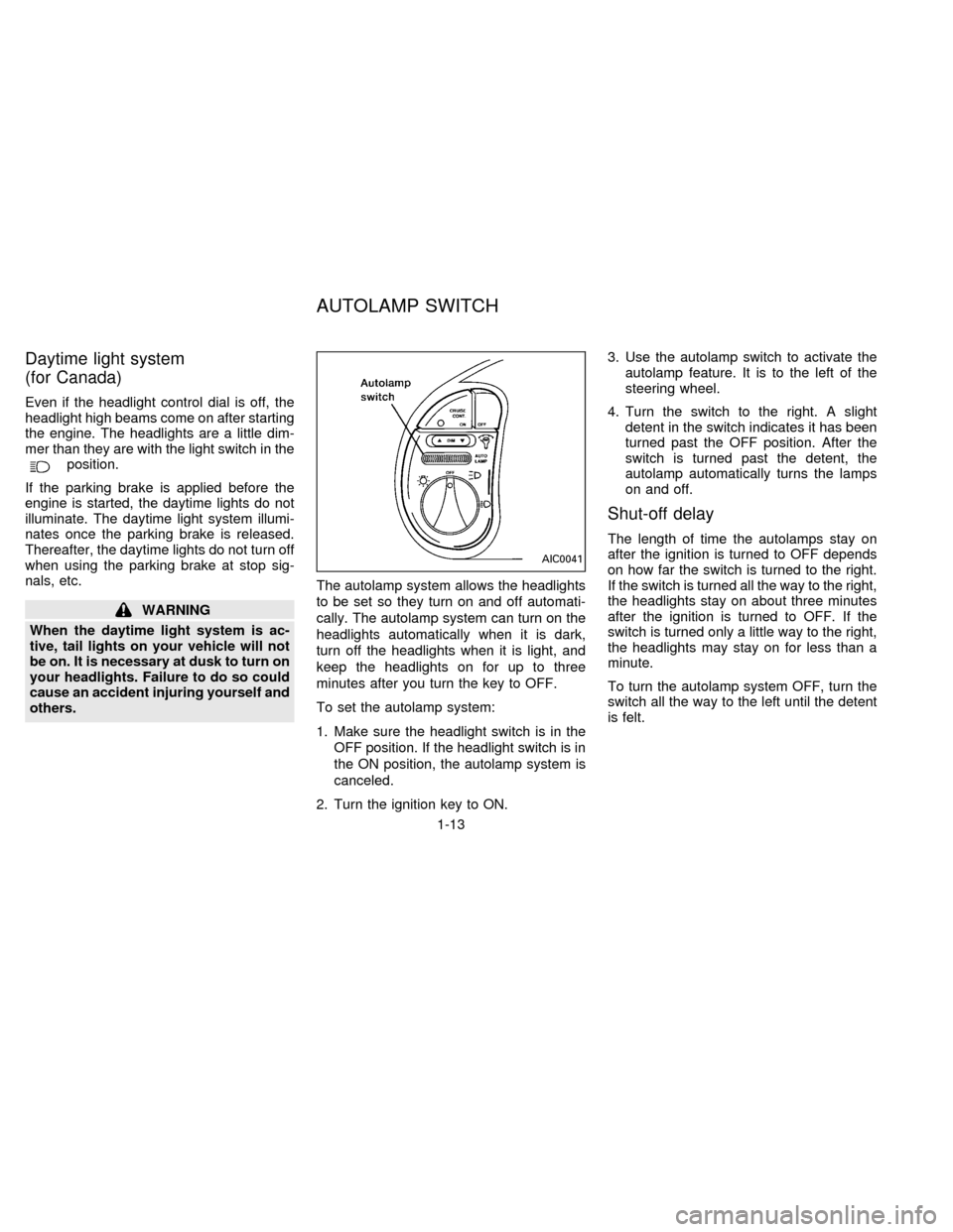
2. Turn the ignition key to ON.3. Use the autolamp switch to activate the
autolamp feature. It is to the left of the
steering wheel.
4. Turn the switch to the right. A slight
detent in the switch indicates it has been
turned past the OFF position. After the
switch is turned past the detent, the
autolamp automatically turns the lamps
on and off.
Shut-off delay
The length of time the autolamps stay on
after the ignition is turned to OFF depends
on how far the switch is turned to the right.
If the switch is turned all the way to the right,
the headlights stay on about three minutes
after the ignition is turned to OFF. If the
switch is turned only a little way to the right,
the headlights may stay on for less than a
minute.
To turn the autolamp system OFF, turn the
switch all the way to the left until the detent
is felt.
AIC0041
AUTOLAMP SWITCH
1-13
ZX
Page 85 of 235

3. Position the lap belt portionlow on the
hips as shown.
4. Pull the shoulder belt portion toward the
retractor to take up extra slack.2-POINT TYPE WITHOUT
RETRACTOR (Center of three-
passenger bench seat)
Fastening the belts
1. Insert the tongue into the buckle until it
snaps.2. To lengthen, hold the tongue at a right
angle to the belt and pull on the belt. To
shorten, pull the free end of the belt away
from the tongue.
APD0131APD0094APD0095
2-56
ZX
Page 86 of 235

3. Position the lap beltlow on the hipsas
illustrated.
Unfastening the belts
To unfasten the belt, press the button on the
buckle.
Selecting correct set of belts
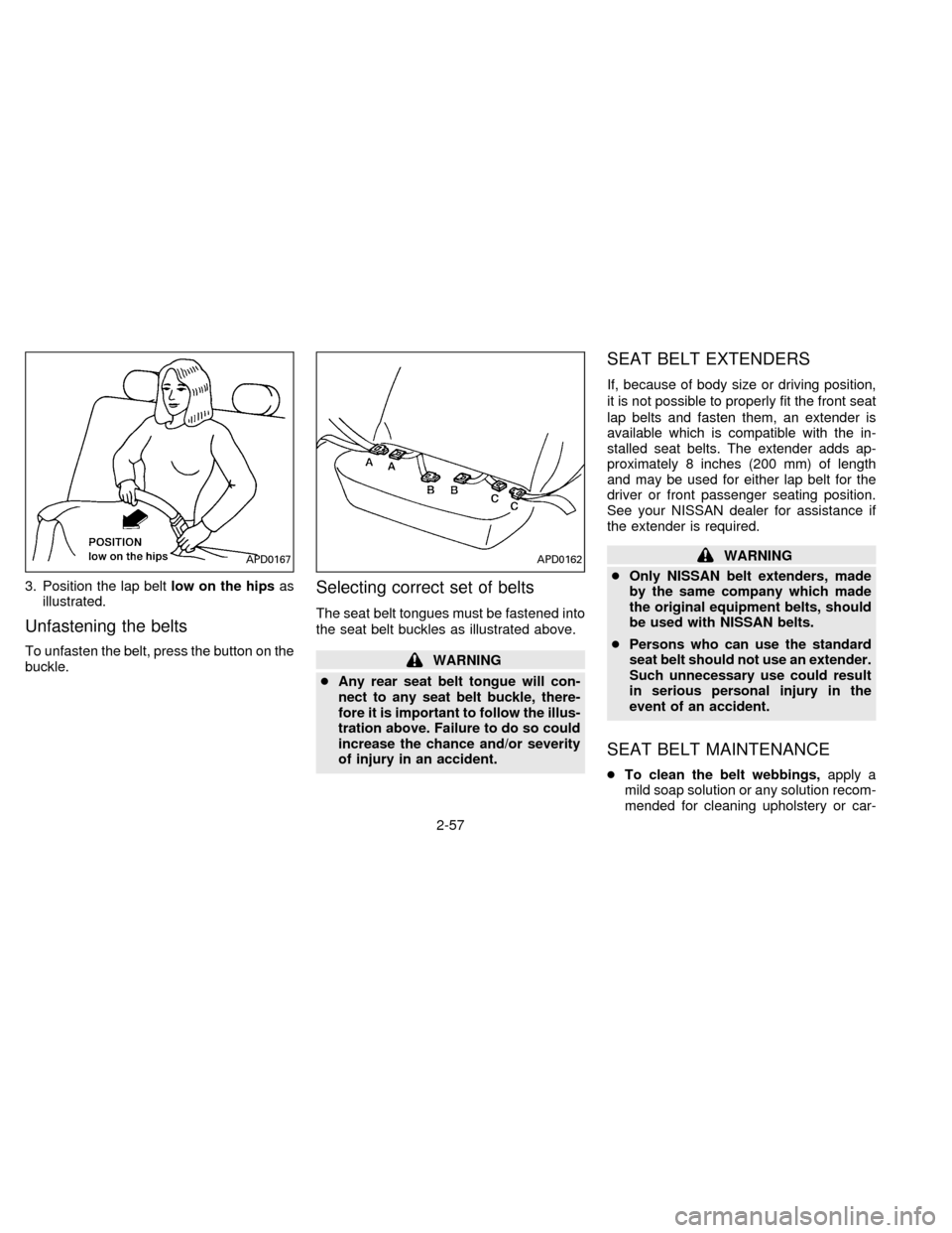
The seat belt tongues must be fastened into
the seat belt buckles as illustrated above.
WARNING
cAny rear seat belt tongue will con-
nect to any seat belt buckle, there-
fore it is important to follow the illus-
tration above. Failure to do so could
increase the chance and/or severity
of injury in an accident.
SEAT BELT EXTENDERS
If, because of body size or driving position,
it is not possible to properly fit the front seat
lap belts and fasten them, an extender is
available which is compatible with the in-
stalled seat belts. The extender adds ap-
proximately 8 inches (200 mm) of length
and may be used for either lap belt for the
driver or front passenger seating position.
See your NISSAN dealer for assistance if
the extender is required.
WARNING
cOnly NISSAN belt extenders, made
by the same company which made
the original equipment belts, should
be used with NISSAN belts.
cPersons who can use the standard
seat belt should not use an extender.
Such unnecessary use could result
in serious personal injury in the
event of an accident.
SEAT BELT MAINTENANCE
cTo clean the belt webbings,apply a
mild soap solution or any solution recom-
mended for cleaning upholstery or car-
APD0167APD0162
2-57
ZX
Page 94 of 235

4. Pull on the third row shoulder belt until all
of the belt is fully extended and a click is
heard. At this time, the belt retractor is in
the automatic locking mode (child re-
straint mode). (The lap/shoulder belt re-
verts back to emergency locking mode
when it is disconnected from the tether
strap and fully retracted.)
5. Allow the belt to retract. A clicking sound
is heard as the belt retracts. This indi-
cates that the retractor is in the automatic
locking mode. Tighten the tether strap to
remove any slack.
6. Before placing the child in the child re-
straint, use force to tilt the child restraint
from side to side, and tug it forward to
make sure it is securely held in place.
7. Check that the retractor is in the auto-
matic locking mode by trying to pull more
belt out of the retractor. If you cannot pull
any more belt webbing out of the retrac-
tor, the belt is in the automatic locking
mode.
8. Check to make sure the child restraint is
properly secured prior to each use. If the
belt is not locking, repeat steps 4 through
7.
INSTALLATION ON THREE-
PASSENGER BENCH SEAT IN
THIRD ROW
A child restraint with a top tether strap may
be placed on the three-passenger bench
seat when the bench seat is in the third row
location. Once the child restraint is properly
secured to the seat (see ``Installation at
second and third row outboard positions'' or
``Installation at three-passenger bench seat
center position'' earlier in this section), fol-
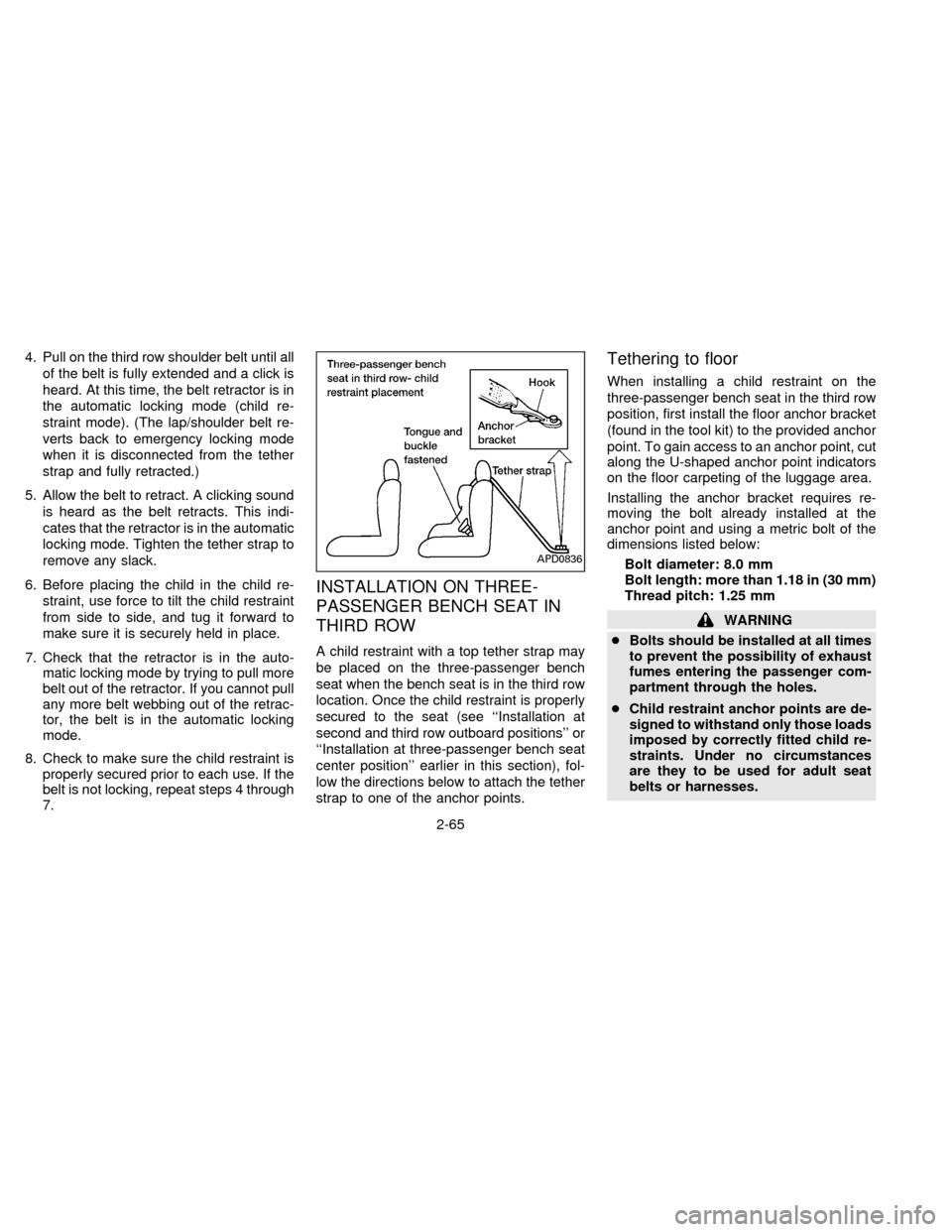
low the directions below to attach the tether
strap to one of the anchor points.
Tethering to floor
When installing a child restraint on the
three-passenger bench seat in the third row
position, first install the floor anchor bracket
(found in the tool kit) to the provided anchor
point. To gain access to an anchor point, cut
along the U-shaped anchor point indicators
on the floor carpeting of the luggage area.
Installing the anchor bracket requires re-
moving the bolt already installed at the
anchor point and using a metric bolt of the
dimensions listed below:
Bolt diameter: 8.0 mm
Bolt length: more than 1.18 in (30 mm)
Thread pitch: 1.25 mm
WARNING
cBolts should be installed at all times
to prevent the possibility of exhaust
fumes entering the passenger com-
partment through the holes.
cChild restraint anchor points are de-
signed to withstand only those loads
imposed by correctly fitted child re-
straints. Under no circumstances
are they to be used for adult seat
belts or harnesses.
APD0836
2-65
ZX
Page 124 of 235

BAL
Balance control allows you to adjust the
sound distribution between the right and left
speakers.
Push the BAL button either
or
; BAL and the setting indicator bar
appear in the display window. Press the
BAL button
to shift the sound to the
right speakers. The single indicator bar
moves to the right of the display window.
Press the BAL button
to shift the
sound to the left speakers. The single indi-
cator bar moves to the left of the display
window. When the indicator bar is in the
center position the sound is equally distrib-
uted between the right and left speakers.
Following balance adjustment, the display
window shows the current setting for three
seconds, then returns to the display prior to
adjustment.
FADE
Fader control allows you to adjust sound
distribution between the front and rear
speakers.
Push the FADE button either
or; FADE and the setting indicator barappear in the display window. Press the
FADE button
to shift the sound to the
front speakers. The single indicator bar
moves to the right of the display window.
Press the FADE button
to shift the
sound to the rear speakers. The single
indicator bar moves to the left of the display
window. When the indicator bar is in the
center position the sound is equally distrib-
uted between the front and rear speakers.
Following fader adjustment, the display win-
dow shows the current setting for three
seconds, then returns to the display prior to
adjustment.
CASSETTE TAPE OPERATIONS
Turn the ignition key to ACC or ON, then
insert the cassette tape into the tape door
by lightly pushing it. Because of the power
loading feature, the cassette tape is auto-
matically pulled into the player and begins
to play.
Do not force the cassette tape into the tape
door. Forcing a tape in or pushing too hard
could damage the player.
When a cassette is inserted into the audio
system, the word TAPE and a cassette sidesymbol (either 1 or 2) illuminate in the
display window.
A cassette tape can be loaded with the
ignition ON whether or not the radio power
is on. Inserting a cassette tape with the
radio power off causes the audio system to
turn on. After the cassette is ejected, the
audio system turns off. Also, the power
antenna (if so equipped) stays in the down
position during cassette tape operation.
The cassette tape automatically changes
directions to play the other side when the
first side is completed.
cTo maintain good quality sound, NIS-
SAN recommends using cassette
tapes of 60 minutes or shorter in
length.
cCassette tapes should be removed
from the player when not in use. Store
cassettes in their protective cases
and away from direct sunlight, heat,
moisture, and magnetic sources.
cDirect sunlight can cause the cassette
to become deformed. The use of de-
formed cassettes may cause the cas-
sette to jam in the player.
3-19
ZX
Page 133 of 235

WARNING
Do not leave children, unreliable
adults, or pets alone in your vehicle.
They could accidently injure them-
selves or others through inadvertent
operation of the vehicle. Also, on hot,
sunny days, temperatures in a closed
vehicle could quickly become high
enough to cause severe or possibly
fatal injuries to people or animals.
EXHAUST GAS (Carbon
Monoxide)
WARNING
Do not breathe exhaust gases; they
contain colorless and odorless carbon
monoxide. Carbon monoxide is dan-
gerous. It can cause unconsciousness
or death.
cIf you suspect that exhaust fumes
are entering the vehicle, drive with
all windows fully open, and have the
vehicle inspected immediately.
cDo not run the engine in closed
spaces such as a garage for any
longer than is absolutely necessary.c
Do not park the vehicle with the en-
gine running for any extended length
of time.
cKeep the rear door and flip-up rear
window closed while driving, other-
wise exhaust gases could be drawn
into the passenger compartment. If
you must drive in this manner for
some reason, take the following
steps.
1. Open all the windows.
2. Set the air recirculate switch to
``OFF'' and the fan control dial at 4
(high) to circulate the air.
cIf electrical wiring or other cable
connections must pass to a trailer
through a seal on the body, follow
the manufacturer's recommendation
to prevent carbon monoxide entry
into the vehicle.
cThe exhaust system and body
should be inspected by a qualified
mechanic whenever:
a. The vehicle is raised for service.b. You suspect that exhaust fumes
are entering into the passenger
compartment.
c. You notice a change in the sound
of the exhaust system.
d.
You have had an accident involv-
ing damage to the exhaust system,
underbody, or rear of the vehicle.
THREE WAY CATALYST
The three way catalyst is an emission con-
trol device installed in the exhaust system.
Exhaust gases in the three way catalyst are
burned at high temperatures to help reduce
pollutants.
WARNING
cThe exhaust gas and the exhaust
system are very hot. While the en-
gine is running, keep people or flam-
mable materials away from the ex-
haust pipe.
cDo not stop or park the vehicle over
flammable materials such as dry
grass, waste paper or rags, as they
may burn easily.
PRECAUTIONS WHEN
STARTING AND DRIVING
4-2
ZX
Page 216 of 235

ModelVG30E
TypeGasoline, 4-cycle
Cylinder arrangement6-cylinder, V slanted at 60É
Bore ý Stroke in (mm) 3.425 ý 3.268 (87.0 ý 83.0)
Displacement cu in (cm
3) 180.62 (2,960)
Firing order1,2,3,4,5,6* (See illustration below)
Idle speed rpm
See the ``Important Vehicle Information'' label on the underside of the hood. Ignition timing (B.T.D.C.) degree/rpm
CO percentage at idle speed
[No air] %
Spark plug
StandardBKR5EY
ColdBKR6EY
Spark plug gap in (mm) 0.031 to 0.035 (0.8 to 0.9)
Camshaft operationTiming belt** (See note below)
Drive belts
[Width ý Length] in (mm)
Generator belt0.7008 ý 33.66 (17.80 ý 855)
Air conditioner compressor0.5606 ý 46.65 (14.24 ý 1,185)
Power steering pump0.5606 ý 40.74 (14.24 ý 1,035)
**NOTE: Periodic maintenance is necessary. Refer to the appropriate periodic
maintenance schedule in Chapter 8.
The spark ignition system of this vehicle meets all requirements of the
Canadian Interference-Causing Equipment Regulations.
ENGINE
9-7
ZX
Page 217 of 235

Road wheel Steel 5-1/2 - JJ ý 15
Aluminum 6-1/2 - JJ ý 15
Offset in (mm) 1.77 (45)
Tire size Conventional P205/75R15 97 S
Cast aluminum* P205/75R15 97 S
P215/70R15 97 T
Spare T125/90D16
P205/75R15 97 S*
P215/70R15 97 T*
*: OptionOverall length in (mm) 189.9 (4,824)
Overall width in (mm) 73.7 (1,871)
Overall height in (mm) 67.6 (1,716)
Front tread in (mm) 63.4 (1,610)
Rear tread in (mm) 63.4 (1,610)
Wheelbase in (mm) 112.2 (2,850)
Gross vehicle weight
rating lb (kg)
See the ``F.M.V.S.S. certification label''
on the left center pillar. Gross axle weight rating
Front lb (kg)
Rear lb (kg)
WHEEL/TIRE SIZE DIMENSIONS AND WEIGHTS
9-8
ZX