1996 HONDA CIVIC Coolant temperature wire
[x] Cancel search: Coolant temperature wirePage 140 of 2189

13. Remove the upper radiator hose' heater hose and
water bYPass hose
WATEREYPASSHOSEUPPERRADIATORHOSE
14.
HEATERHOSE
Remove the engine wire harness connectors and
wire harness clamps from the cylinder head and the
intake manifold.
o Four fuel injector connectors
. Engine coolant temperature (ECT) sensor con-
nector
a
a
a
ECT switch connector
ECT gauge sending unit connector
Throttle position sensor connector
Manitold absolute pressure (MAP) sensor con-
nector
Primary heated oxygen sensor (primary HO2S)
connector
Secondary heated oxygen sensor (secondary
HO2S) connector (D16Y7 engine)
Exhaust gas recirculation (EGR) valve lift sensor
connector (D16Y5 engine)
. VTEC solenoid valve connector (Dl6Y5, D16Y8
engrnes)
. VTEC pressure switch connector (D16Y5. D16Y8
engrnes,
. ldle air control (lAC) valve connector
15.Remove the spark plug caps and distributor from
the cylinder head.
Remove the uPPer bracket.
NOTE:
. Use a jack to support the engine before the
upper bracket is removed.
. Make sure to place a cushion between the oil
pan and the jack.
12 x 1.25 mm
74 N.m {7.5 kgf m.
sil lbl.ftl
UPPERBRACKET
'17. Remove the cylinder head cover'
CYLINDERHEAD COVER
(cont'd)
6-29
Page 179 of 2189
WATER BYPASS
HOSE
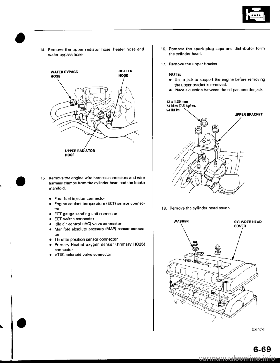
14. Remove the upper radiator hose, heater hose and
water bvpass hose.
HEATER
Remove the engine wire harness connectors and wlre
harness clamps from the cylinder head and the intake
manifold.
Four fuel injector connector
Engine coolant temperature (ECT) sensor connec-
tor
ECT gauge sending unit connector
ECT switch connector
ldle air control (lAC) valve connector
Manifold absolute pressure (MAP) sensor connec-
tor
Throttle position sensor connector
Primary Heated oxygen sensor (Primary HO2S)
connecror
VTEC solenoid valve connector
15.
a
a
a
a
a
\
16.
17.
Remove the spark plug caps and distributor form
the cylinder head.
Remove the upper bracket.
NOTE:
. Use a jack to support the engine before removing
the upp€r bracket is removed.
. Place a cushion between the oil panandthejack.
12 x 1.25 fin74 N.m 17.5 kgtm,
UPPER BRACKET
18. Remove the cylinder head cover.
{cont'd)
6-69
Page 360 of 2189
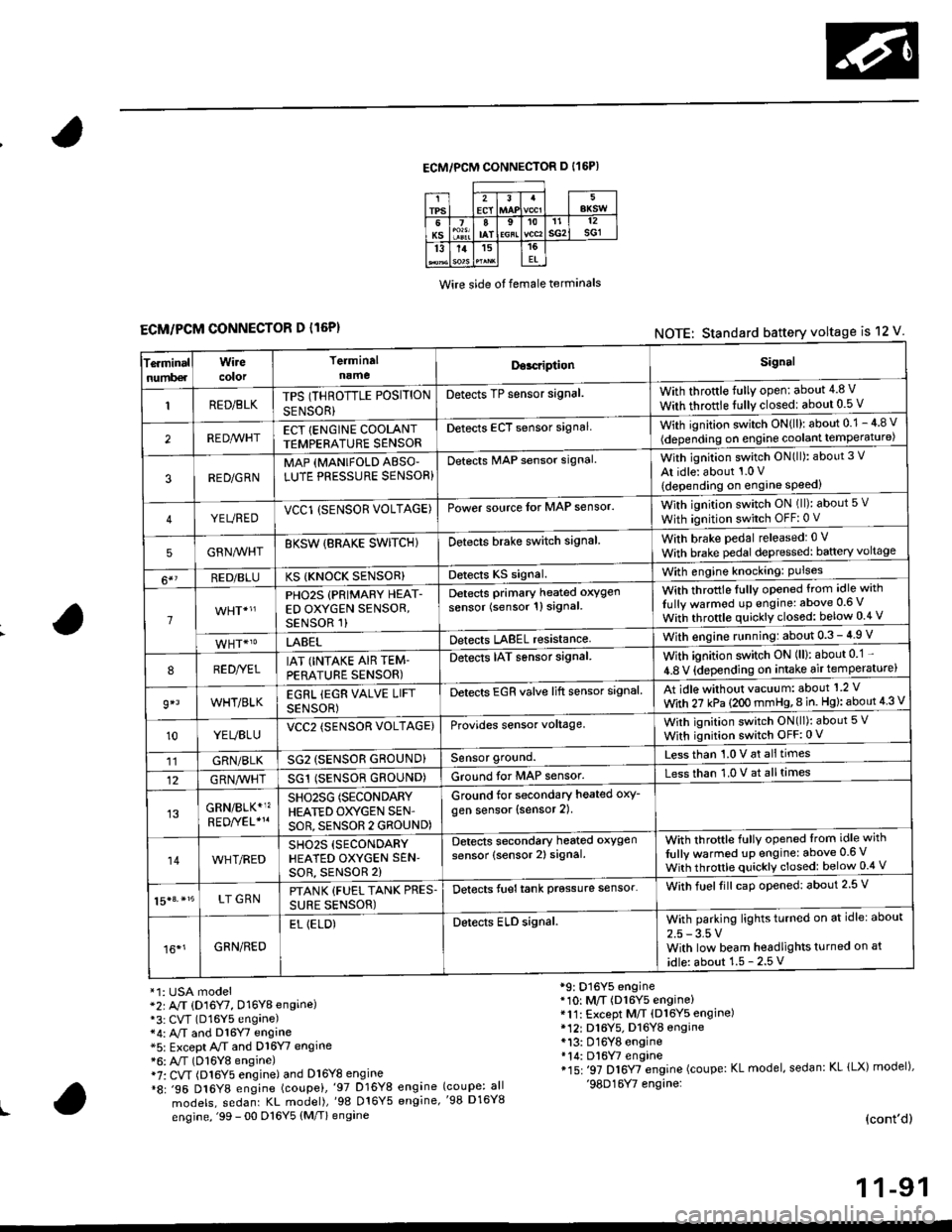
ECM/PCM CONNECTOR D I16P)
Wire side ot female terminals
ECM/PCM CONNECTOR D l16P)NOTE: Standard battery voltage is 12 V
Te.minalnumb€r
Wirecolor
Terminaln!meDor.riptionSignal
RED/BLKTPS (THROTTLE POSITION
SENSOR}
Detects TP sensor signal.With throttle fully open: about 4.8 V
With throttle fully closedl about 0.5 V
REDA/VHTECT {ENGINE COOLANTTEMPERATURE SENSORDetects ECT sensor signalWith ignition switch ON{ll): about 0.1 - 4 8 v
(depending on engine coolant lempe ratu re)
3RED/G RNMAP {MANIFOLD ABSO'LUTE PRESSURE SENSOR}Detects MAP sensor signal.With ignition switch ON(ll): about 3 V
At idle: about 1.0 V
{depending on engine speed)
YEUREDVCCl (SENSOR VOLTAGE)Power source lor MAP sensor.With ignition switch ON (ll): about 5 v
With ignition switch OFF: 0 V
5GRNMHTBKSW {BRAKE SWITCHIDetects brake switch signalWith brake pedal released: 0 v
With brake pedal depressed: baftery voltage
6*?RED/BLUKS {KNOCK SENSOR}Detects KS signal.With engine knocking: Pulses
1
PHO2S (PRIMARY HEAT-ED OXYGEN SENSOR,SENSOR 1)
Detects Primary heated oxygen
sensor (sensor 1l signal
With throttle fullv opened from idle with
Iully warmod up engine: above 0.6 V
With throttle quickly closed: below 0.4 v
LABELDetects LABEL resistanceWith engine r!nning:about 0.3 - 4.9 V
8RED//ELIAT (INTAKE AIR TEM-PERATURE SENSOR)
Detects IAT sensor signal.With ignition switch ON (ll): about 0 1 -
4.8 V {depending on intake air temperature)
9*lWHT/BLKEGRL iEGR VALVE LIFT
SENSOR)
Detects EGR valve lift sensor signalAt idle without vacuum: about'1 2 V
With 27 kPa (2OO mmHg,8 in. Hg): about 4 3 V
10YEUBLUVCC2 (SENSOR VOLTAGE)Provides sensor voltage,With ignition switch ON(ll): about 5 V
With ignition switch OFF:0 V
11GRN/BLKSG2 (SENSOR GROUND}Sensor ground.Less than 1.0 V at alltimes
12G RN,4/1r'HTSG1 (SENSOR GROUND)Ground for MAP sensor.Less than 1.0 V at alltimes
GRN/BLK*1?SHO25G (SECONDARY
HEATED OXYGEN SEN'
SOR, SENSOR 2 GROUND)
Ground for secondary heated oxy-
gen sensor (sensor 2).
14WHT/REDSH02S (SECONDARY
HEATED OXYGEN SEN'soR, sENsoR 2)
Detects secondary heated oxygen
sensor (sensor 2) signal.With throftle fully opened lrom idle with
fully warmed up engine: above 0.6 V
With throttle quickly closed: below 0.4 V
15|3. *15LT GRNPTANK {FUEL TANK PRES.
SURE SENSOR)
Detects fueltank prgssure sensor'With fuelfill caD opened: about 2.5 V
16*1GRN/RED
EL (ELD)Detects ELD signal.With parking lights turned on at idle: about
2.5 - 3.5 VWith low beam headlights turned on at
idle: about 1.5 - 2.5 V
*1: USA model*2r A/T (D16Y7, D16Y8 engine)*3: CVT (D16Y5 engane)*4: A,/T and Dl6Y7 engine*5: Except A/T and D16Y7 engine*6: A"/T (D16Y8 engine)i7: CVT (Dl6Y5 engine) and Dl6Y8 engine*8: .96 D16Y8 engine (coupei,'97 D16Y8 engine
models, sedanr KL model),'98 016Y5 engine,
engine, '99 - 00 D16Y5 (M/T) engine
*9: D16Y5 engine*10: M/T (D16Y5 engine)*11: Except M/T (Dl6Y5 engine)* 12r D16Y5. D16YB engine*13: D16Y8 engine*14: Dl6W engine*15: '97 D16Y7 engine (coupe: KL model, sedan: KL lLX) model),'98D16Y7 engine:(coupe: all'98 D16Y8
(cont'd)
1 1-91
Page 398 of 2189
|.
'f
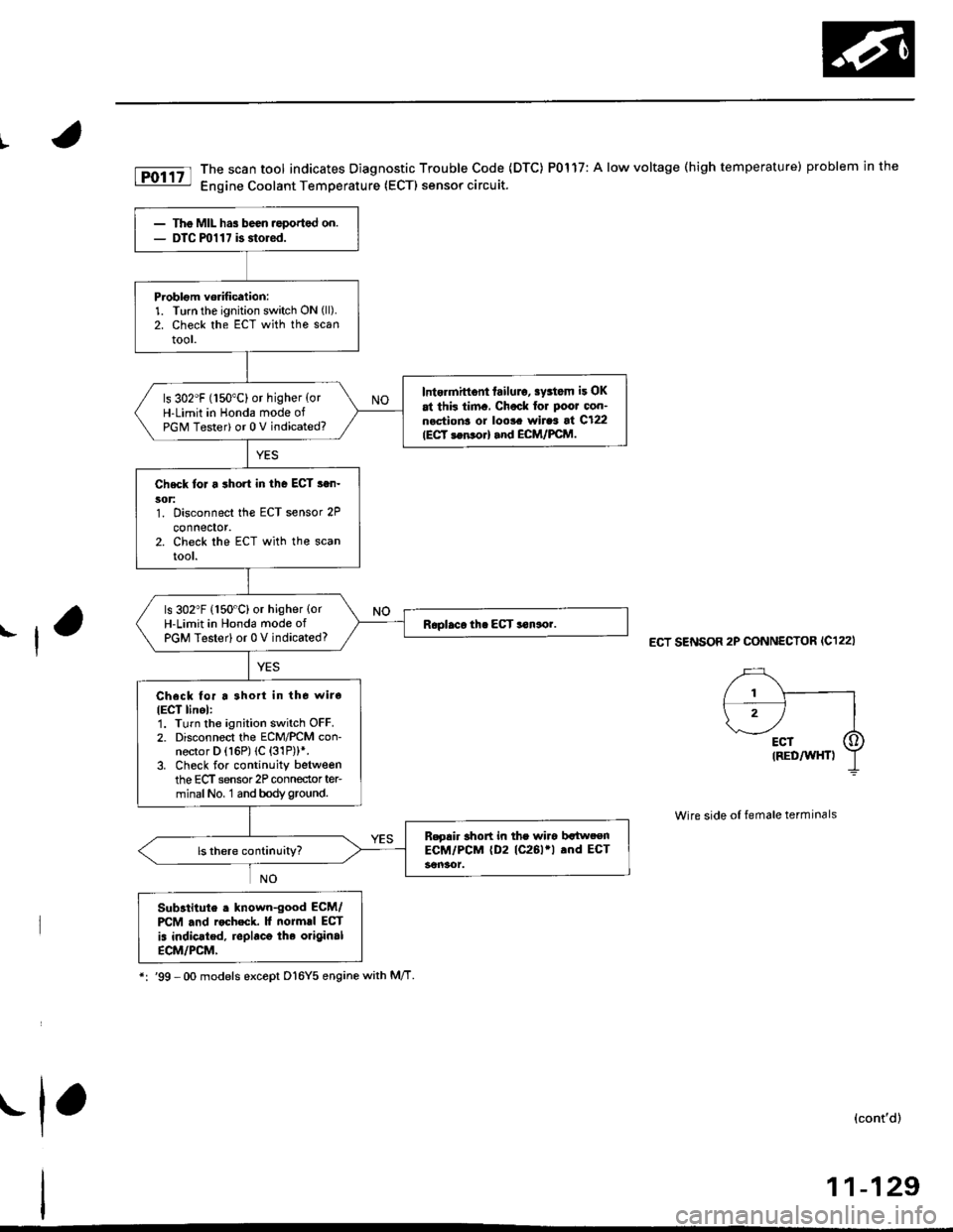
fD;r.tt The scan tool indicates Diagnostic Trouble Code (DTC) P0117: A low voltage (high temperature) problem in the|jg Engine Coolant Temperature (ECTI sensor circuit.
ECT SENSOR 2P CONNECTOR (C122I
Wire side of female terminals
Substitute . lnown-good ECM/PCM .nd rocheck. It normrl ECT
is indic.ted, replaco the original
ECM/PCM,
*:'99 -Oo models except D16Y5 enginewith M/T
(cont'd)
11-129
The MIL has been ,eported on.DTC ml 1 7 is storod.
Problom vorification:1. Turn the ignition switch ON (ll).
2. Check the ECT with the scantool.
Intermittont failulo, sy3tom it OK
at thk tim., Chock for Poor oon-n.ctions or loo!. wiraa at C122IECT 3en orl and ECM/FCM.
ls 302"F (150"C) or higher {orH-Limit in Honda mode ofPGM Tester) or 0 V indicated?
Check toJ a short in the ECT s.n-5('t:1. Disconnect the ECT sensor 2P
connector.2. Check the ECT with the scanrool.
ls 302"F (150"C) or higher {orH-Limit in Hond6 mode ofPGM Testerl or 0 V indicated?
Check for a 3hort in tho wiro
IECT linel:1. Turn the ignition switch OFF.2. Disconnect the ECM/PCM con-nector D (16P) (C {31P))*.3. Check for continuity betweenthe ECT sensor 2P conneclor ter-minalNo, 1 and bodyground.
B.gair short in the wiro bltweenECM/PCM (D2 (C261'l .nd ECT
.1,
Page 399 of 2189
PGM-FI System
Engine Coolant Temperature (ECT) Sensor
('96 - 98 Models,'99 - 00 D16YS engane with M/T) (cont'd)
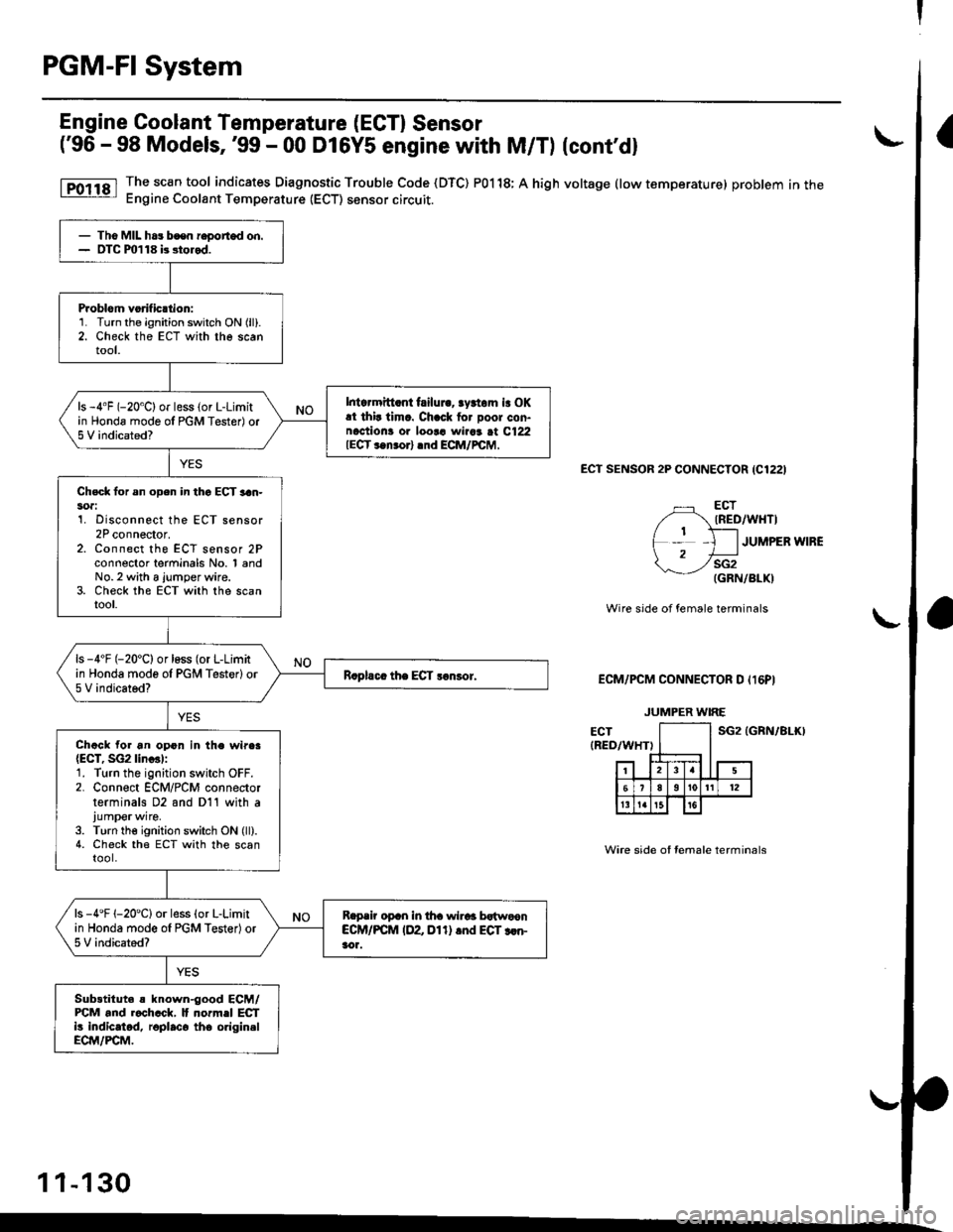
The sc€n tool indicates Diagnostic Trouble Code (DTC) P0118; A high voltage (low temperature) problem in theEngine Coolant Temperature (ECT) sensor circuit.
ECt SENSOR 2P CONNECTOR {C1221
ECTIRED/WHTI
JUMPER WIRE
sG2(GRN/BLK)
Wire side of female terminals
ECM/PCM CONNECTOR D Il6PI
sG2 tGRN/81r0
Wire side of Iemale terminals
- Tho MIL ha3 bcen r€oorted on.- OTC m118 b stored.
Problom vorificttion:1. Turn the ignition switch ON (ll).
2. Check the ECT with the scantool.
Intcrmitt.nt failui.. rydom is OKat thir timc. Chack for Door con-naction! or loor! wiaar at C122IECT ..n.orl .nd ECM/rcM,
ls -4"F (-20'C) or less (or L-Limitin Honda mode ol PGM Tester) or5 V indicated?
Chsck lor sn open in thc ECT 3an-soa:1. Disconnect the ECT sensor2P connector.z. Lonnecr rne ELt sensor zFconnector terminals No. 1 andNo.2 with a jumper wire.3. Check the ECT with the scantool.
ls -4'F (-20'C) or loss (or L-Limitin Honda mode ol PGM Testerlor5 V indicated?
Chack for an opon in the wire.{ECT, SG2lin..l:1. Turn the ignition switch OFF.2. Connect ECM/PCM connectorterminals D2 and D11 with ajump€rwire.
3. Turn the ignition switch ON (ll).4. Check the ECT with the scantool.
ls -4'F 1-20'Clor less (o. L-Limitin Honda mode ol PGM Tester)or5 V indicated?
Reprir oprn in tha wirar bstwoonCCM/PCM IDZ Dl1) .nd EGT rcn-aor.
Sub3titut. s known-good ECM/FCM and r.chcck, It normel ECTi! indicatod, roplaco tho origin.lECM/PCM.
JUMPER WIRE
1 1-130
Page 400 of 2189

PGM-FI System
t
I
Engine Coolant Temperature (ECT) Sensor
('99 - 00 Models except Dl6Y5 engine with M/Tl
The scan tool indicates Diagnostic Trouble Code (DTC) P0118: A high voltage (low temperature) problem in the
Engine Coolant Temperature (ECT) sensor circuit.
ECT SENSOR 2P CONNECTOR {C122)
ECT(RED/Wr{T)
JUMPER IVIRE
sG2{GRN/BLK)
wire side of female terminals
ECM/PCM CONNECTOB C 131PI
The MIL has been reported on,
oTC P0118 is stored.
Problem verilication:1. Turn the ignition switch ON (ll).
2. Check the ECT with the scan
tool.
lntormittent failuro, systom is OK
at thb timo. Check lor poor con'nections or 10036 wiraa at C122
{ECT ssnsorl and ECM/rcM.
ls -4'F (-20"C) or less lor L-Limit
in Honda mode o{ PGM Tester) or
5 V indicated?
Check for an open in the Efi sen'
sori1. Disconnect the ECT sensor 2P
connector,2. Connect the ECT sensor 2P
connector terminals No, 1 andNo. 2 with a jumper wire.3. Check the ECT with the scantool.
ls -4"F 1-20"C) or less (or L-Limit
in Honda mode of PGM Tester) or
5 V indicated?
Check for sn open in the wires
IECT. SG2 linesl:1. Turn the ignition switch OFF.2. Connect ECM/PCM connectorterminals C18 and C26 with ajumper wire.3. Turn the ignition switch ON (ll).
4. Check the ECT with lhe scantooi.
Rspair opon in th6 wiros bstwoon
ECM/PCM (Cl8, C26l and ECT
3ensot.
ls -4'F {-20"C) or less (or L-Limit
in Honda mode of PGN4 Tester) or
5 V indicated?
Substitute 6 known-good ECM/PCM and recheck. l{ no.mal EcT
is indicatod, .eplace the originalECM/PCM.
JUMPER WIRE
Wire side of female terminals
11-131
Page 558 of 2189

\
EVAP CONTROLCANISTER VENT SHUTVALVE 2P CONNECTOR IC141I
Wire side of temale terminals
ECM,/PCM CONNECTORS
tG1IBLK/WHT}
A973X -
0/r1 - XXXXX
Wire side of femaletermrnats
\
?,T-t
fl
VACUUMPUMP/GAUGE, 0 -30 in.Hg
\(cont'd)
11-289
{From page l1 288}
{To page 11-290)
Ch€ck the vac[um when cold:1, Disconnect the vacuum hoseshown from the EVAP controlcanister and connect a vacuumgauge to the hose.2. Start the engine and allow it
to idle.NOTEi Engine coolant temperature must be below 154"F(68'C) or Ay'C switch OFF.3. Ouickly raise the engine speedto 3,000 rpm.
(From page 11-288)
Check for an open in tha wire(lGt linol:1. Turn the ignition switch OFF.2. Disconnect the 2P connectorfrom the EVAP control canis-ter vent shut valve.3. Turn the ignition switch ON lll).4. Measure voltage between theEVAP control canister vent shut
valve 2P connector terminalNo.2 and bodyground.
Repair open in the wire betweenthe EVAP control canister ventshut valve .nd the No. 15 ALTER-NATOR SP SENSOR {7.5 A)fu3e.
ls there battery voltage?
Ch€d( for an op€n in the wiie IVSVlinel:1. Turn the ignition switch OFF.
2. R€connect the 2P connectorto the EVAP control canistervent shut valve,3. Turn the ignition switch ON (ll).
4. Measure vo ltage betweenECM/PCM connector termi-nals A4 and 82.
Repair open in the wire bctweenthe EVAP control canistor ventshut valve and lhe ECM/PCM{44t.
ls there battery voltage?
Rcolaco tho EVAP control canis.t6r vent shut valvo.
a t32P)
-
Page 1486 of 2189
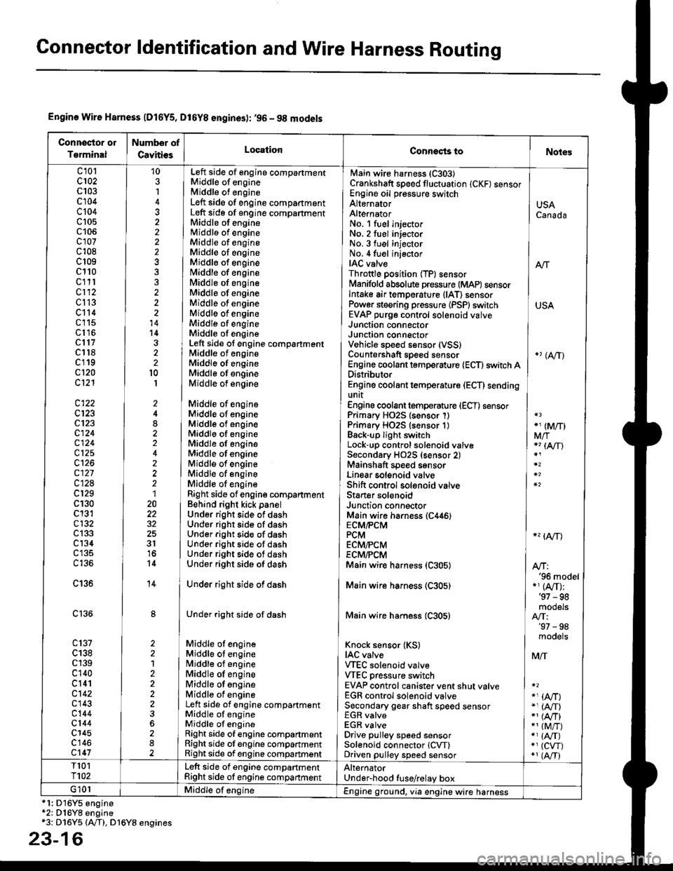
Connector ldentification and Wire Harness Routing
Engine Wire Harness lD16Y5, D16Y8 enginss): '96 - 98 models
Connector or
Torminal
Numbsr of
CavitissLocationConnects toNot€s
c 101c102c103c104c104c105c106c107c108c 109c110c111c112c113c114c115c116cl17c118c119c120cl21
c122c123cl23c124
c125
c127c12Ac129c130c131c132c 133c134c135
c136
c138c139c140c 141c142c 143c144cl44c145c'146cl47
10
1
22
14l4322l0I
2
2
2
2120
3l
14
14
1222
2
2
22
Left side of engine compartmentMiddle of engineMiddle of engineLeft side of engine companmentLeft side of engine compartmentMiddle of engineMiddle of engineMiddle of engineMiddle of engineMiddle of enginefvliddle of engineMiddle of engineMiddle of engineMiddle of engineMiddle of engineMiddle of engineMiddle of engineLeft side of engine compartmentMiddle of engineMiddle of engineMiddle of engineMiddle of engine
Middle of engineMiddle of engineMiddle of engineMiddle of engineMiddle of engineMiddle of engineMiddle of engineMiddle of engineMiddle of engineRight side of engine companmentBehind right kick panelUnder right side of dashUnder riOht side of dashUnder right side of dashUnder right side of dashUnder right side of dashUnder right side of dash
Under right side of dash
Under right side of dash
Middle of engineMiddle ot enginel iddle of engineMiddle of engineMiddle of ongineMiddle of engineLeft side of engine compartmentMiddle of engineMiddle of engineRight side of engine compartmentRight side of engine compartmentRight side of engine compartment
USACanada
Afi
USA
-' (A/r)
Main wire harness (C303)Crankshaft speed fluctuation (CKF) sensorEngine oil pressure switchAlternatorAlternatorNo. 'l fuel injectorNo. 2 fuel injectorNo.3 fuel injectorNo. 4 fuel injectorIAC valveThrottle position (TP) sensorl\4anifold absolute pressure (MAP) sensorIntake air temperature (lAT) sensorPower steering pressure {PSPI switchEVAP purge control solenoid valveJunction connectorJunction conn€ctorVehicle speed sensor {VSS}Countershaft speed sensorEngine coolant temp€rature (ECT) switch ADistributorEngine coolant temperature (ECT) sendingunrtEngine coolant temperature (ECT) sensorPrimary HO2S (sensor'l)Primary HO2S (sensor 1)Back-up light switchLock-up control solenoid valveSecondary HO2S (sensor 2)Mainshaft speed sensorLinear solgnoid valveShift control solsnoid valveStarter solenoidJunction connectorMain wire harnesE (C446)ECM/PCMPCMECMiPCMECM/PCMMain wire harness (C305)
Main wire harness (C305)
Main wire harness (C305)
Knock sensor (KS)IAC valveVTEC solenoid valveVTEC pressure switchEVAP control canister vent shut valveEGR control solenoid valveSecondary gear shaft speed sensorEGR valveEGR valveDrive pulley speed sensorSolenoid connector {CVT)Driven pulley speed sensor
*, (M/T)M/T*" INT\
*, tAtf)
NT:'96 model*,(A,/T):'97 - 98mooets
moqets
M/T
-1 (l,/T)*, (A,/T)-,(4,/T)*1 {M/T)*, (A,/T)*1 (CW)*, (A,T)
T101r102Left side of engine companmentRight side of engine companmentAlternatorUnder-hood fuse/relay boxG 101Middle of engineEngine ground, via engine wire harness
2
*1: Dl6Y5 engine*2: D16Y8 engine*3: D16Y5 (Ay'T), D16Y8 engines
3-16